
Circuits

a circuit and circuit technology, applied in the field of double balanced mixers, can solve the problems of affecting the detection of the desired signal in zero-if (direct conversion), and reducing the detection efficiency of the desired signal

Active Publication Date: 2008-02-07
HUANG QIUTING +1
View PDF43 Cites 32 Cited by
  • Summary
  • Abstract
  • Description
  • Claims
  • Application Information

AI Technical Summary

Benefits of technology

[0017] An advantage of the invention is that it can cope with blocking signals without the use of an expensive SAW filter. More particularly the circuit provided can all be fabricated using integrated circuit technology, preferably in a single integrated circuit.
[0018] The invention is of use, amongst other things, in mobile telephones or in any other kind of mobile terminal station, for example, PDA's with wireless mobile data connectivity or a similarly enabled laptop computer; in the latter the wireless connection is provided, for example, in a PC card, which may for example send data using GPRS.

Problems solved by technology

Although there is usually a reasonably large frequency separation between the desired and blocking signals, passive RF filters prior to the mixer can only attenuate the blocking signals to a limited extent.
Even-order nonlinearity in the RF receiver in general and mixers in particular can therefore adversely affect the detection of the desired signal in zero-IF (direct conversion) and low-IF receiver architectures because the said desired signal is directly frequency-shifted to the baseband before sufficient amplification.
Inevitable mismatch of a practical implementation of the positive and negative signal paths of the mixer, however, results in imperfect cancellation of the envelope-detected blocking signal.
Since RF devices tend to be small in order to achieve high frequency operation, matching accuracy among them is limited.
Typical achievable IP2 by a fully integrated mixer is 40˜50 dBm, which is insufficient for advanced applications such as WCDMA, in which a mobile phone's transmitter signal leaks through the duplexer into the phone's own receiver, where it acts as a blocking signal.
Perfect balance is however not generally possible for a double balanced mixer without separately adjusting the pair of transconductor transistors and each pair of switching transistors.
Performed outside the normal operation of the mixer, the method also requires memory elements, A / D and D / A converters and preferably an RF test signal source, which adds a large cost overhead.

Method used


Image

  • Circuits
  • Circuits
  • Circuits

Examples


Embodiment Construction

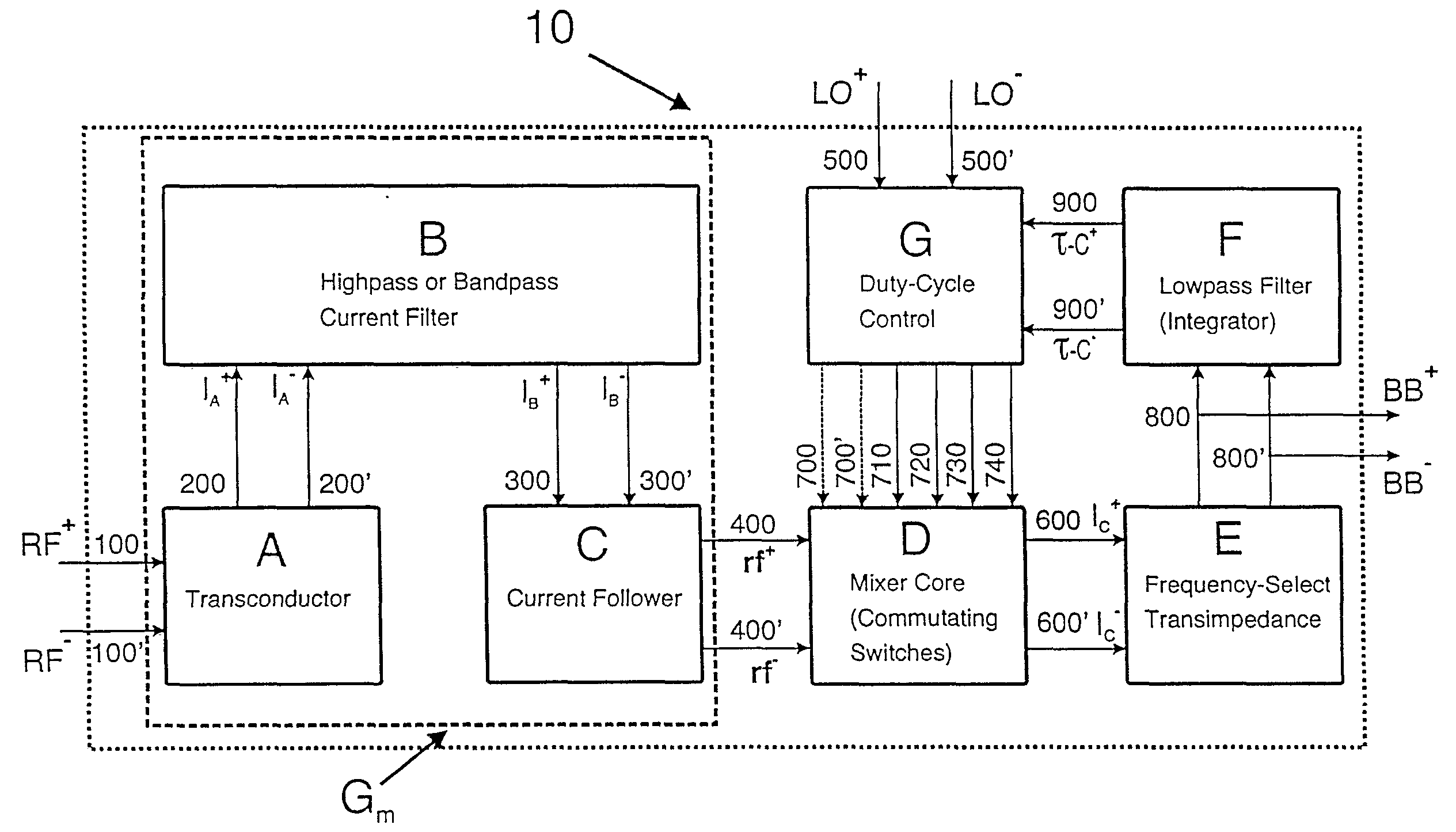
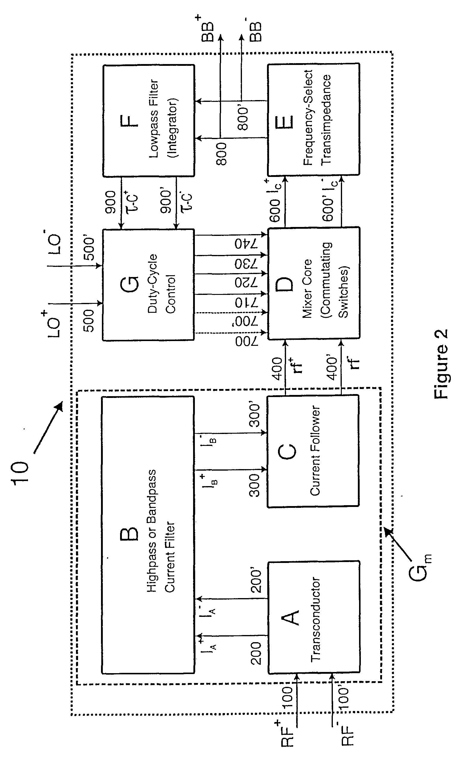
[0041] In the preferred embodiment, a mixer circuit in accordance with the invention comprises, as shown in FIG. 2, a transconductor A, a passive two-port network B, a current follower C, a mixer core D, a transimpedance stage E, a lowpass filter F and a duty-cycle control block G. In summary the mixer circuit operates as follows.

[0042] At its boundary the overall mixer circuit 10 has a first overall input port RF, a second overall input port LO and an overall output port BB. The input port RF receives the radio frequency signal carrying the information to be frequency-shifted—it will, of course also receive any blocking signal present. The input port LO receives a local oscillator signal. The output port BB provides the frequency-shifted output signal.

[0043] The input port RF is provided by the input of transconductor A. The transconductor A converts the received RF signal into a differential RF current at its output. That differential RF current enters the input port of passive ...


PUM


Abstract

A double balanced mixer has a DC detection circuit connected to receive the output of the mixer core. The detected level is applied to adjust the duty cycle of the transistors of the mixer core. In one example, this adjusting level is added to the local oscillator signals that are applied to the core. In another example, the level is applied to adjust the threshold of the transistors of the mixer core. In a further example, the duty cycle of the local oscillator signals is adjusted before it is applied to the mixer core Also provided is an input stage for a double balanced mixer core, which comprises a transistor having a low pass filter as a feedback circuit.

Description

FIELD OF THE INVENTION [0001] This invention relates to mixers typically used in radio frequency (RF) receivers. In particular it relates to a double balanced mixer with high even-order intercept points. BACKGROUND OF THE INVENTION AND RELATED ART [0002] A mixer is an essential building block in a radio frequency (RF) receiver for translating in frequency a modulated signal from being centered about the RF carrier or an intermediate frequency (IF) to being centered about DC, where it is referred to as the baseband (BB) signal. In the remainder of this document references to RF frequencies or RF signals equally apply to mixers whose inputs are signals at IF frequencies. The elements that actually perform the frequency translation are commutating switches (mixer core) that direct an RF current alternately to the opposite sides of the load impedance. Mathematically the differential voltage across the load is equal to the RF current multiplied by the differential load impedance and an a...

Claims


Application Information

Patent Timeline
IPC IPC(8): H03D7/14
CPCH03D7/1441H03D7/1433H03D7/1458H03D2200/0084H03D7/1491H03D2200/0043H03D2200/0047H03D7/1483H03D7/14
Inventor HUANG, QIUTINGROGIN, JURGEN
Owner HUANG QIUTING
Learn More