[0008]According to one aspect of the present invention, there is provided a method of reducing or blocking
blood flow to a selected blood vessel, or a selected part of a wall thereof, particularly for treating an aneurysm, an
arteriovenous malformation, or a dural malformation, or for devascularizing a blood vessel feeding the tumor, such method comprising: deploying in the selected blood vessel an expandable member having a contracted condition for manipulation within the blood vessel, and expandable to an expanded condition in the blood vessel for reducing or blocking blood flow through the blood vessel or the selected part of the wall thereof, and thereby to promote coagulation of blood within the selected blood vessel or part of the wall thereof; and applying a local stimulus to the interior of the selected blood vessel or part of the wall thereof effective to initiate or accelerate coagulation of blood therein.
[0013]In one described preferred embodiment, the permeable mesh-like tube, while in the contracted state, is moved through the blood vessel to a position wherein its opposite sides
straddle the opposite sides of the aneurysm (or other malformation) in which the coagulation of the blood is to be promoted. This side of the permeable mesh-like tube facing the downstream direction is expanded; the optic
fiber tip is deployed into the aneurysm (or other malformation); and then
light energy is applied to the
optical fiber to initiate or accelerate coagulation of blood therein while the permeable mesh-like tube prevents emboli resulting from the coagulation from moving through the blood vessel in the downstream direction.
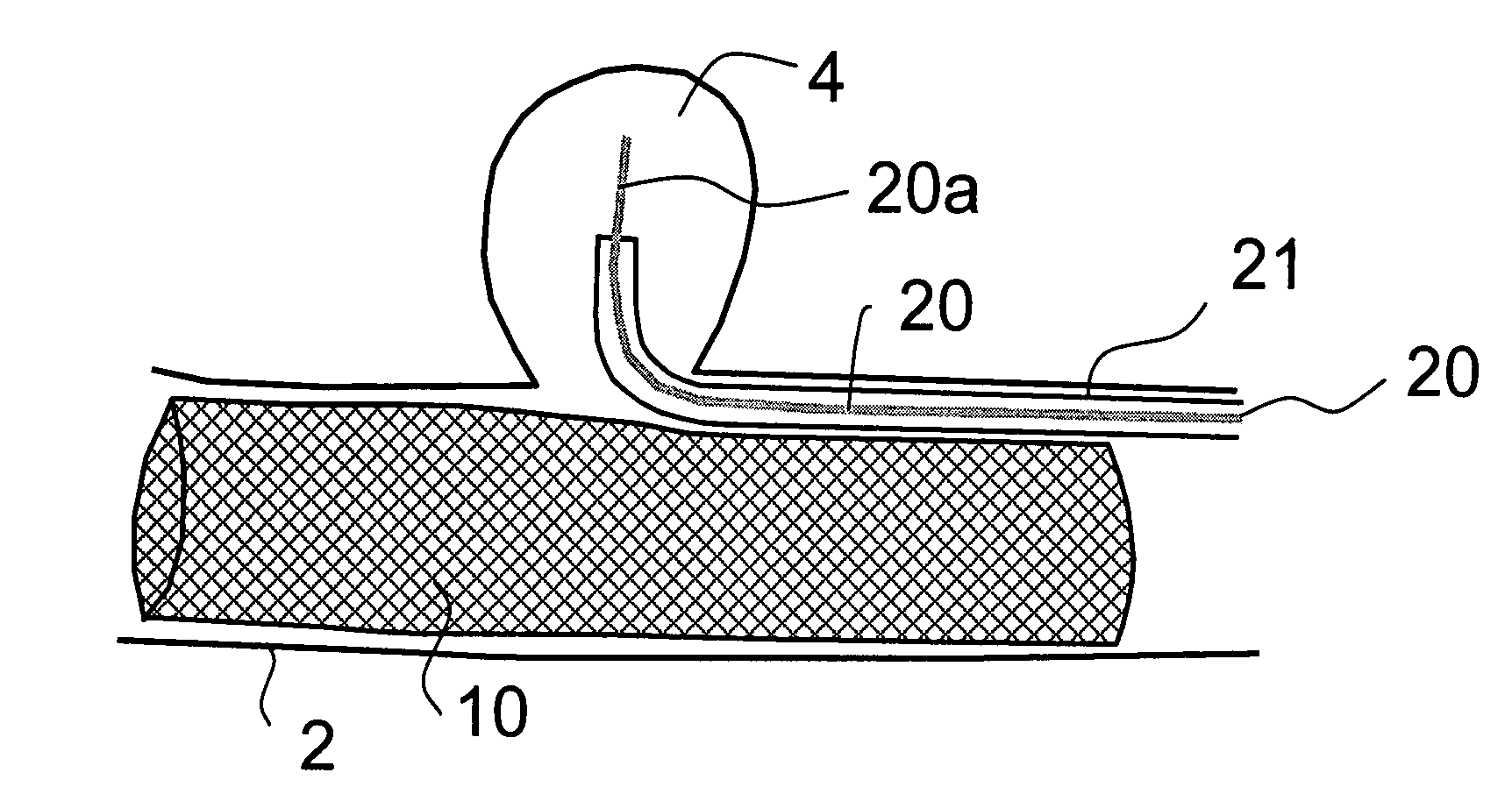
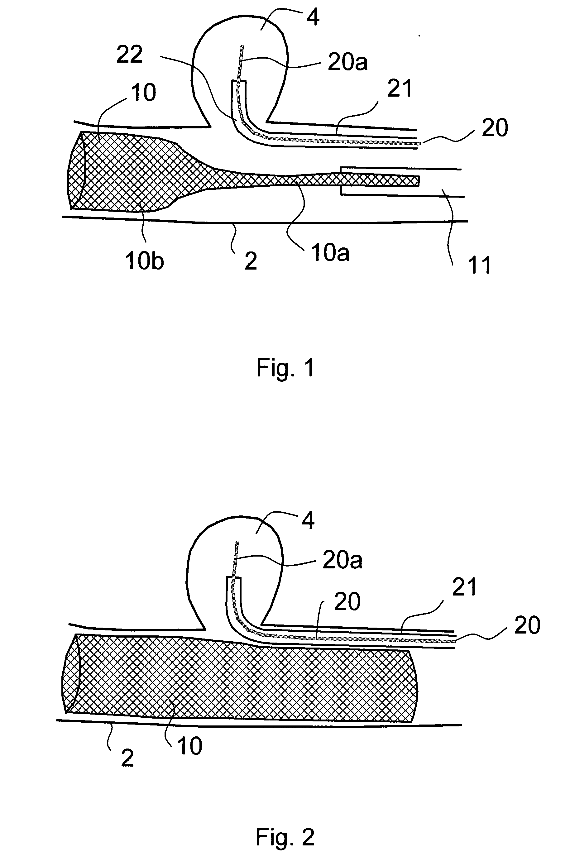
[0014]In a second described preferred embodiment, the permeable mesh-like tube, while in the contracted state, is moved through the blood vessel to a position wherein its opposite sides
straddle the opposite sides of the aneurysm (or other malformation); the optic
fiber tip is deployed into the aneurysm by moving the
optical fiber between the outer surface of the permeable mesh-like tube and the inner surface of the blood vessel; the permeable mesh-like tube is then expanded to fix it within the blood vessel straddling the aneurysm; and
light energy is then applied to the
optical fiber to cause its tip to initiate or accelerate coagulation of the blood within the aneurysm, while the permeable mesh-like tube prevents emboli resulting from the coagulation from moving via the tube into the blood vessel.
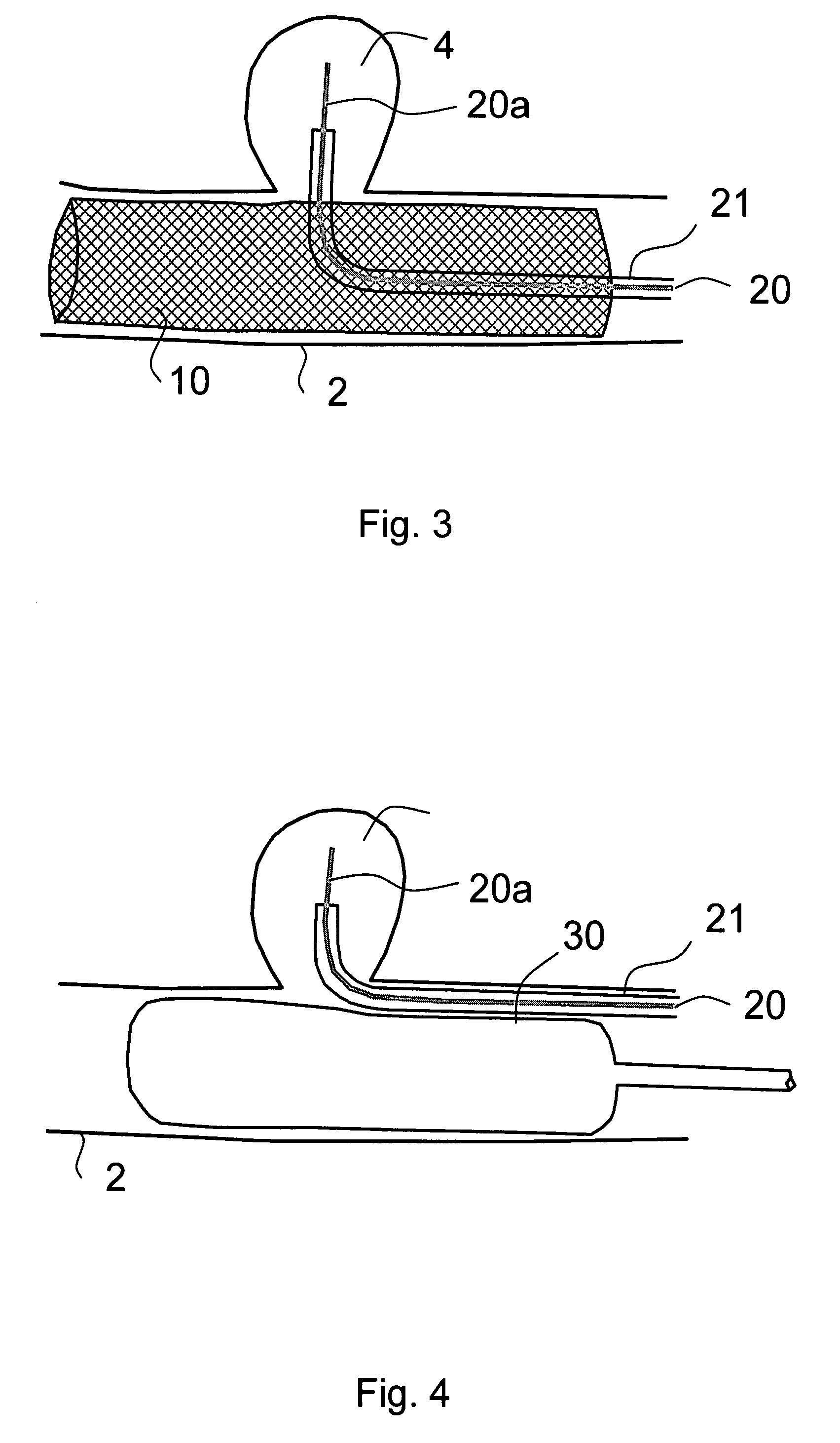
[0016]In a fourth described preferred embodiment, particularly in
narrow neck aneurysms, a compliant
occlusion balloon, while in the contracted state, is moved through the blood vessel to a position wherein its opposite sides
straddle the opposite sides of the aneurysm (or other malformation); the optic
fiber tip is deployed into the aneurysm by moving the optical fiber between the outer surface of the
balloon and the inner surface of the blood vessel; the balloon is then expanded to fix it within the blood vessel straddling the aneurysm; and
light energy is then applied to the optical fiber to cause its tip to initiate or accelerate coagulation of the blood within the aneurysm, while the balloon prevents emboli resulting from the coagulation from moving into the blood vessel.
[0017]In a fifth described preferred embodiment, particularly in
narrow neck aneurysms, a compliant
occlusion balloon, while in the contracted state, is moved through the blood vessel to a position downstream to the aneurysm (or other malformation) and then expanded to fix it within the blood vessel distal to the aneurysm; the optic fiber tip is deployed into the aneurysm; and light energy is then applied to the optical fiber to cause its tip to initiate or accelerate coagulation of the blood within the aneurysm, while the balloon prevents emboli resulting from the coagulation from moving downstream into the distal blood vessels.
[0018]According to another aspect of the present invention, there is provided a method of treating an aneurysm, arteriovenous or a dural malformation in a blood vessel, or devascularizing blood vessels feeding a tumor, by deploying in the blood vessel leading to the malformation or the tumor a temporary
occlusion balloon of
biocompatible material, and inflating the balloon such as to temporarily stop blood flow to the malformation. Via a center tube in the balloon a light-
energy absorption agent, or a biochemical thrombosing agent, is applied to the interior of the malformation including all
layers of the wall before advancing a fiber optic with a diffusing tip through the center tube into the malformation.
Light energy is then applied as local stimulus to the interior of the malformation while
saline is flushed in the gap between the fiber optic and the center tube to provide an optically translucent or transparent field and prevent
thermal damage to the
arterial wall. Slow deflation of the balloon is then commenced such as to initiate or accelerate coagulation of blood now perfusing the malformation.

