Syringe for use with injectors and methods of manufacturing syringes and other devices

a technology of syringes and injectors, which is applied in the field of syringes for use with injectors and to methods of manufacturing syringes and other devices, can solve the problems of degrading optical properties, increasing costs, and difficulty in manufacturing syringes with desirable transparent optical properties, so as to reduce thickness, reduce thickness, and reduce thickness

Active Publication Date: 2008-02-07
BAYER HEALTHCARE LLC
View PDF18 Cites 74 Cited by
  • Summary
  • Abstract
  • Description
  • Claims
  • Application Information

AI Technical Summary

Benefits of technology

[0018]A removable closure can be formed on a distal end of the outlet section during injection molding. The closure can, for example, be removably connected to the outlet section via a wall section of reduced thickness.
[0019]In another aspect, the present invention provides a method of forming a syringe for use with an injector including injection molding a polymeric material to form a removable closure integrally with an outlet section or opening of the syringe. The removable closure can, for example, be formed during injection molding of a preform for the syrin

Problems solved by technology

Historically, it has been difficult to manufacture syringes with desirable transparent optical properties that exhibit sufficient strength for use with front-loading, pressure jacketless injectors.
Typically, to achieve suitable strength, the syringe walls must be thickened during manufacture, which increases costs and, depending upon the material, can degrade optical properties.
However, in the current injection molding p

Method used


Image

  • Syringe for use with injectors and methods of manufacturing syringes and other devices
  • Syringe for use with injectors and methods of manufacturing syringes and other devices
  • Syringe for use with injectors and methods of manufacturing syringes and other devices

Examples


Embodiment Construction

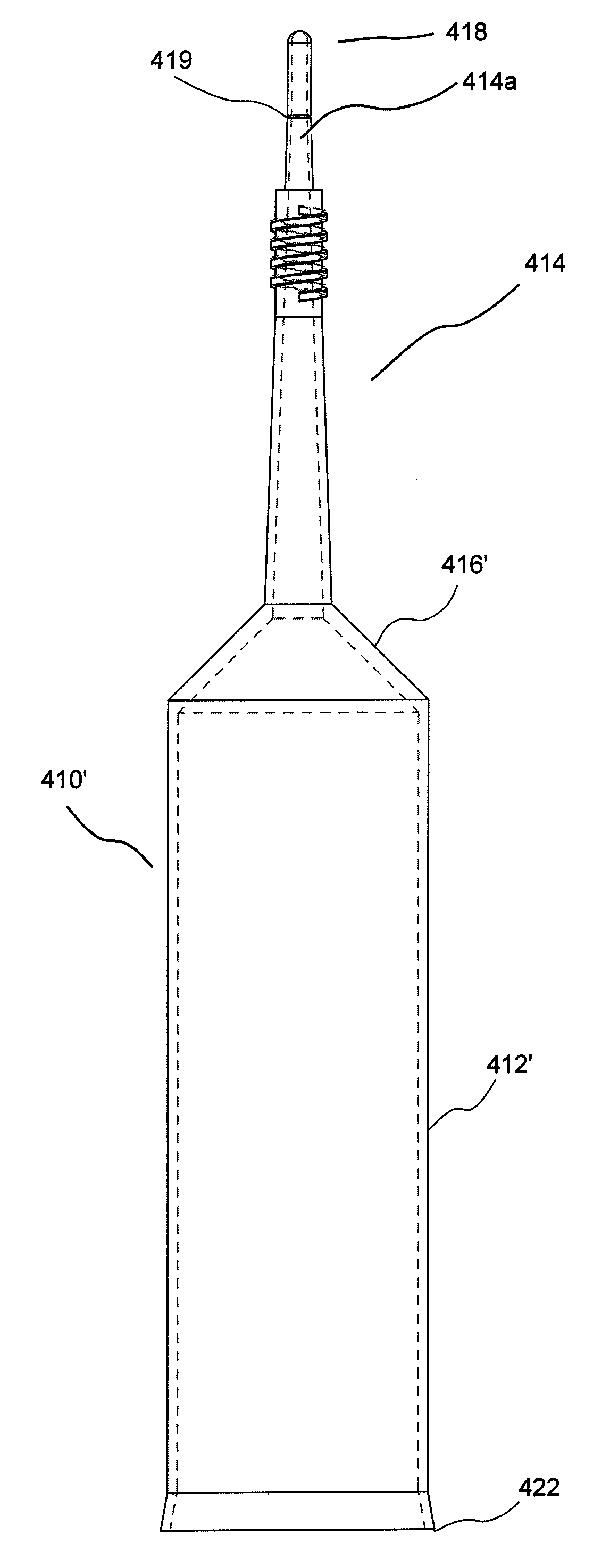
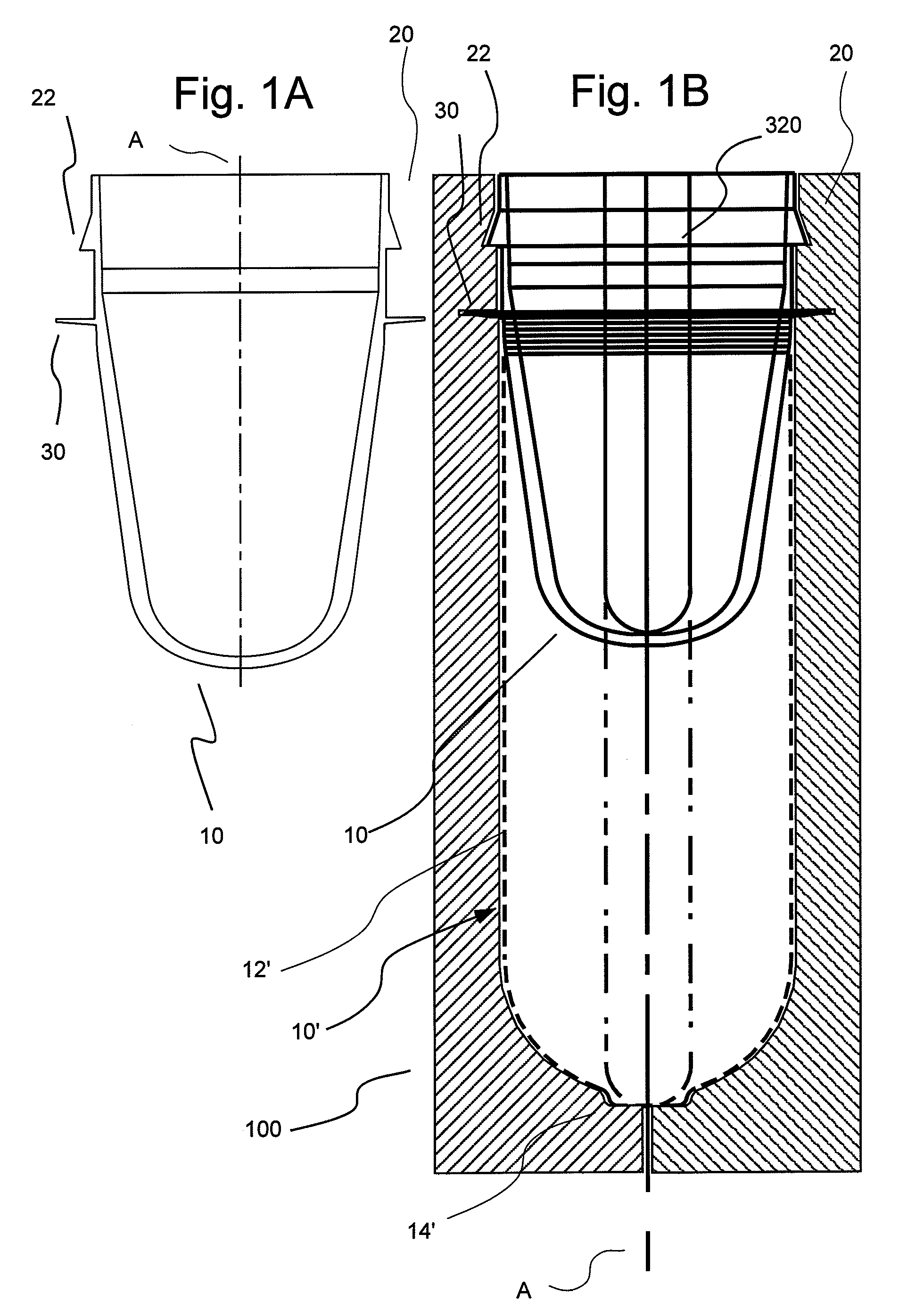
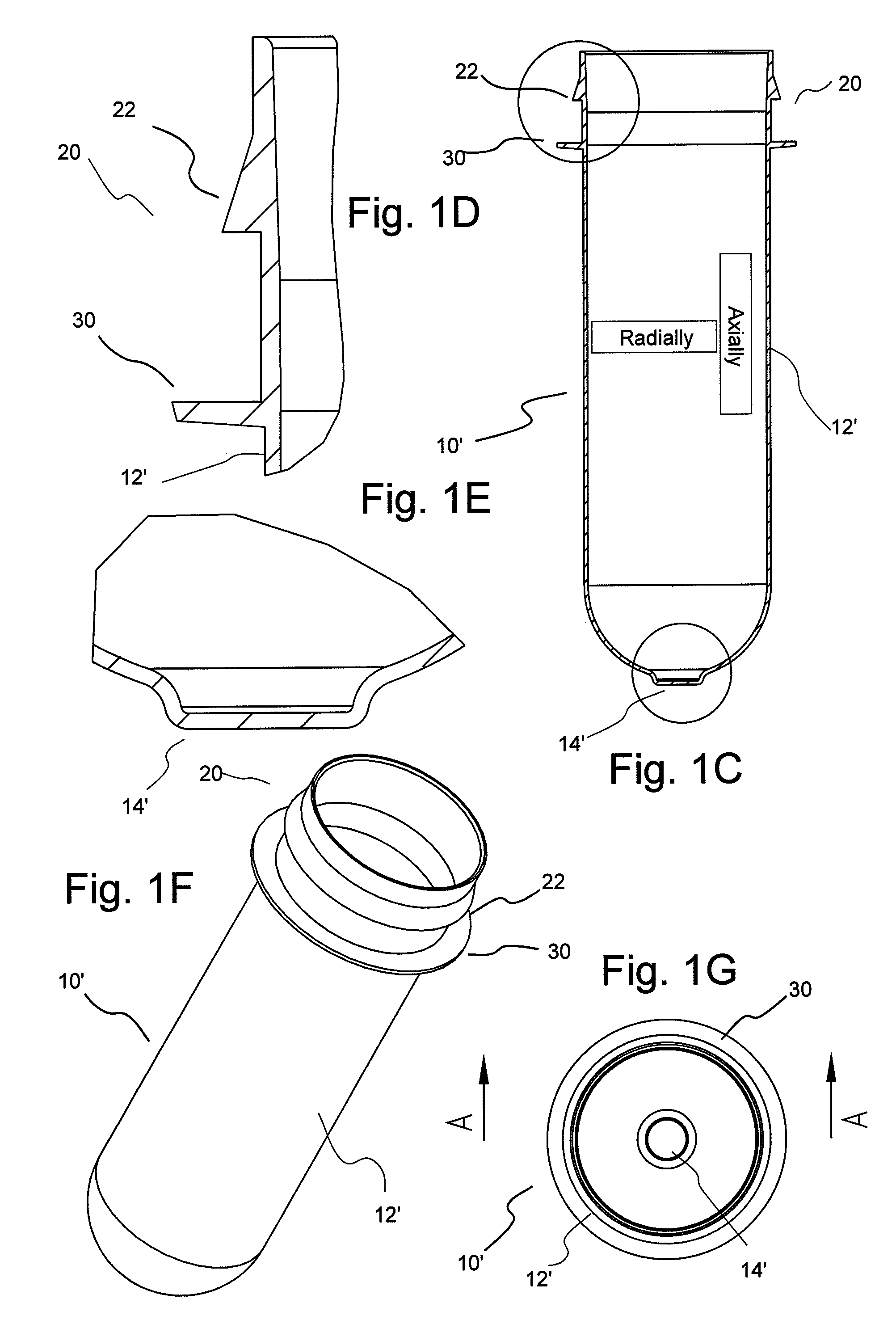
[0051]In general, the present invention provides hollow article devices such as syringes and methods of manufacture of such devices using blow molding processes. The present invention is discussed below primarily with reference to representative embodiments of syringes for injection of a fluid into a patient. However, one skilled in the art appreciates that the methods of the present invention can be used to form a number of hollow article devices (including, for example, medical flow path elements or devices).

[0052]Blow molding is a method of forming hollow articles from polymeric (thermoplastic) materials. Simplifying, the blow molding process involves forming a heated tube within a mold cavity using a pressurized gas (typically, compressed air). The three most common methods of blow molding are extrusion blow molding, injection blow molding and injection-stretch blow molding. In extrusion blow molding, tubes or parisons are extruded into alternating open mold halves and then blow...


PUM

PropertyMeasurementUnit
Thicknessaaaaaaaaaa
Thicknessaaaaaaaaaa
Pressureaaaaaaaaaa

Abstract

A syringe for use in a pressurized injection of a fluid includes a syringe barrel including a polymeric material having undergone expansion via blow molding. An inner diameter of the syringe barrel can, for example, be sufficiently constant (over at least a portion of the axial length of the syringe) that a plunger slidably positioned within the syringe barrel and in generally sealing contact with an inner wall of the syringe barrel can be used within the syringe barrel to generate a pressure of at least 1 psi within the syringe barrel. In several embodiment, the inner diameter of the syringe barrel is sufficiently constant to generate a pressure of at least 100 psi, at least 300 psi, or even at least 500 psi within the syringe barrel. A method of forming a syringe includes the steps of: injection molding at least one polymeric material to form a preform; placing the preform into an blow mold die; and expanding at least a portion of the preform while heating the preform within the die to form a barrel of the syringe. The syringes can be formed to withstand relatively high pressures as described above. The at least one polymeric material can, for example, be polyethyleneterephthalate, cyclic olefin polymer, polypropylene, polystyrene, polyvinylidene chloride, polyethylene napthalate and/or nylon.

Description

CROSS REFERENCE TO RELATED APPLICATION(S)[0001]This application claims an invention which was disclosed in Provisional Application No. 60 / 821,314, filed Aug. 3, 2006, entitled “Syringe for Use with Injectors and Methods of Manufacturing Syringes”. The benefit under 35 USC § 119(e) of the United States provisional application is hereby claimed, and the aforementioned application is hereby incorporated herein by reference.BACKGROUND OF THE INVENTION[0002]The present invention relates generally to syringes for use with injectors and to methods of manufacturing syringes and other devices and, particularly, to syringes manufactured by blow molding and to methods of blow molding syringes and other devices.[0003]In many medical procedures, such as drug delivery, it is desirable to inject a fluid into a patient. Likewise, numerous types of contrast media (often referred to simply as contrast) are injected into a patient for many diagnostic and therapeutic procedures for example, gene therap...

Claims


Application Information

Patent Timeline
IPC IPC(8): A61M5/178B29C45/14
CPCA61M5/007B29L2031/7544A61M5/14566B29B11/08B29B11/10B29B11/14B29B2911/14053B29B2911/14066B29B2911/1408B29B2911/14093B29B2911/14113B29B2911/1412B29B2911/1414B29B2911/14146B29B2911/14166B29B2911/14173B29B2911/14326B29B2911/14333B29B2911/14366B29B2911/144B29B2911/1442B29B2911/1446B29B2911/14486B29C49/0073B29C49/04B29C49/06B29C49/12B29C49/22B29C49/221B29K2023/086B29K2023/12B29K2025/00B29K2027/08B29K2067/00B29K2077/00A61M5/14546Y10T428/1352Y10T428/1379B29C2949/3008B29C2949/3012B29C2949/3026B29C2949/3016B29C2949/302B29C2949/3036B29C2949/3034B29C2949/3028B29C2949/3044B29C2949/3042B29C2949/0767B29C2949/0762B29C2949/077B29C2949/0776B29C2949/073B29C2949/078B29C2949/072B29C2949/3032B29C49/071B29C2949/0715A61M5/3129A61M2207/10
Inventor HAURY, JOHN A.RHINEHART, EDWARD J.BELCHER, SAMUEL L.
Owner BAYER HEALTHCARE LLC
Why Eureka
Try Eureka