Transmission line with heat transfer ability

a technology of heat transfer ability and transmission line, which is applied in the field of systems and devices for delivering energy to tissue, can solve the problems of not being able to travel a sufficient length of the device to reach, unsuitable or unsuitable for many applications, etc., and achieves the effect of reducing the diameter of the device, retaining its small size, and increasing the overall diameter of the devi

Active Publication Date: 2008-02-07
NEUWAVE MEDICAL
View PDF101 Cites 134 Cited by
  • Summary
  • Abstract
  • Description
  • Claims
  • Application Information

AI Technical Summary

Benefits of technology

[0010] In some embodiments, the systems, devices, and methods of the present invention provide coaxial transmission lines that allow cooling by circulation of a coolant material through the coaxial transmission line (e.g., circulation of a coolant material through coolant tubes positioned within the coaxial cable) (e.g., through flowing of a coolant material through the dielectric of the coaxial component). In some embodiments, the devices are configured to minimize the diameter of the device, while permitting the passage of the coolant. This is accomplished, in some embodiments, by positioning of deformable coolant tubes (e.g., Kapton tubes) within the coaxial cable. In such embodiments, a triaxial cable comprises a dielectric material positioned between an inner conductor and a middle coaxial shield, and deformable coolant tubes positioned between the middle coaxial shield and an outer conductor. The devices are not limited to a particular middle coaxial shield. In some embodiments, the middle coaxial shield is a thin (e.g., 0.25 mm, 0.5 mm, 1.0 mm, 1.2 mm, 1.4 mm, 1.6 mm, 2.5 mm, etc.) flexible metal (e.g., copper). The devices are not limited to particular coolant tubes. In some embodiments, the coolant tubes are deformable such that upon positioning within a coaxial tube, the tubes will deform but retain an ability to circulate a coolant material (e.g., nitrogen, carbon dioxide, water). In some embodiments, the coolant tubes are Kapton tubes or similar polymer films. As such, the devices providing coolant tubes provide not only an ability to control the temperature of the device (e.g., through circulation of coolant material through the coolant tubes), but also provide an ability to retain its small size (e.g., due to the use of deformable coolant tubes that do not increase the overall diameter of the device).
[0011] In some embodiments, the devices are configured to minimize the diameter of the device, while permitting the passage of the coolant, by replacing strips of a solid dielectric material with channels through which a coolant is transferred. In some embodiments, the channels are generated by stripping the dielectric material along the length of the coaxial cable from one or more (e.g., two, three, four) zones. With the removed portions of the dielectric material creating channels for transfer of the coolant, the stripped component fits within a smaller outer conductor than it did prior to removal of the dielectric material (see FIG. 1, element 300). This provides for smaller devices with all of the advantages derived therefrom. In some embodiments where multiple channels are employed, coolant transfer may be in alternative directions through one or more of the channels. An advantage of the devices is that the diameter of the coaxial cable does not need to be increased to accommodate coolant. This permits the use of cooled devices that are minimally invasive and permits access to regions of a body that are otherwise inaccessible or accessible only with undesired risk. The use of coolant also permits greater energy delivery and / or energy deliver for prolonged periods of time.

Problems solved by technology

Existing devices, to provide appropriate energy delivery and heat management, are large in diameter, making them undesirable or unsuitable for many applications.
In some embodiments, the antenna and / or tip are not contacted with the cooling material (e.g., the cooling material is only flowed to the feed line, and does not travel a sufficient length of the device to reach the antenna).

Method used


Image

  • Transmission line with heat transfer ability
  • Transmission line with heat transfer ability
  • Transmission line with heat transfer ability

Examples


Embodiment Construction

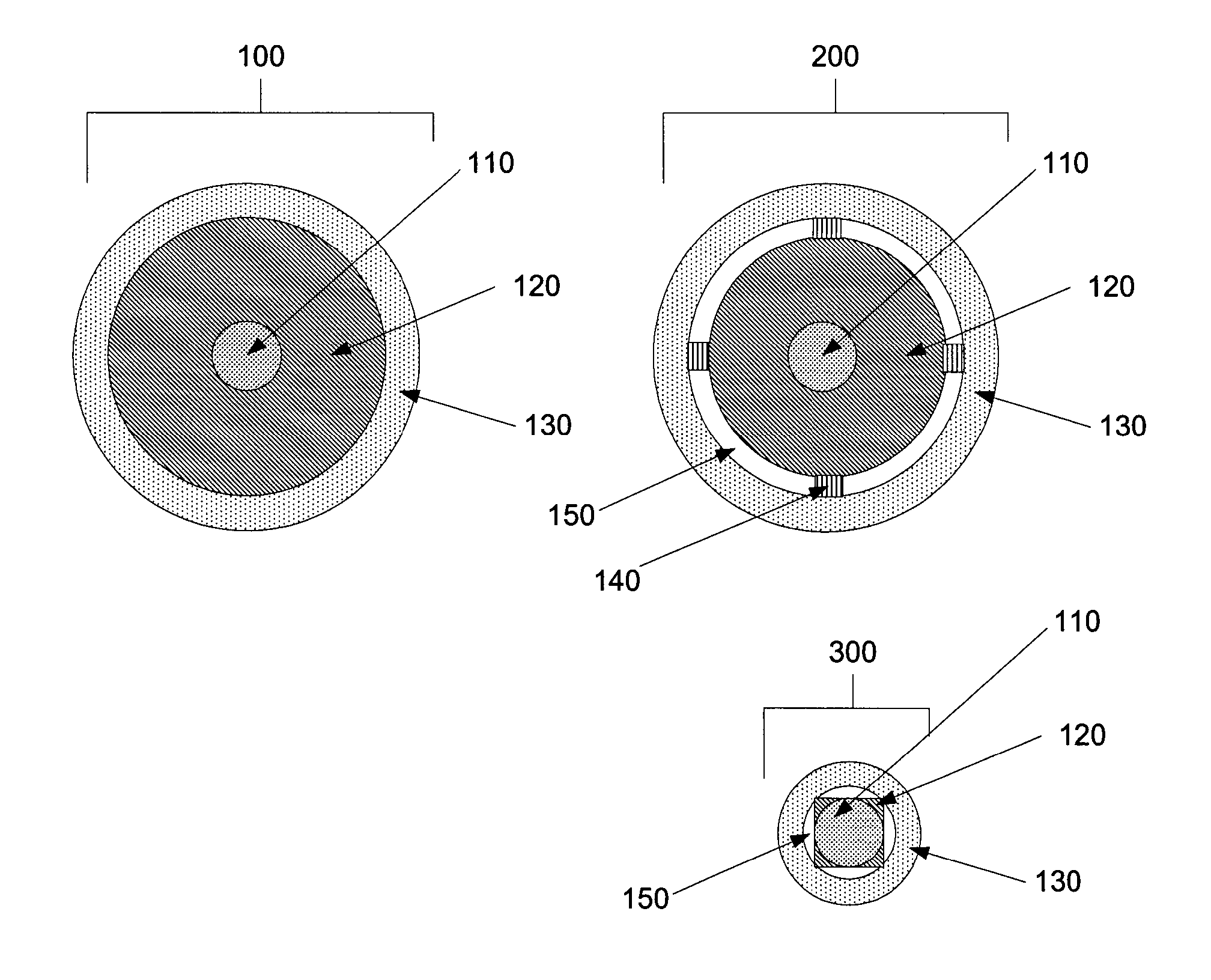
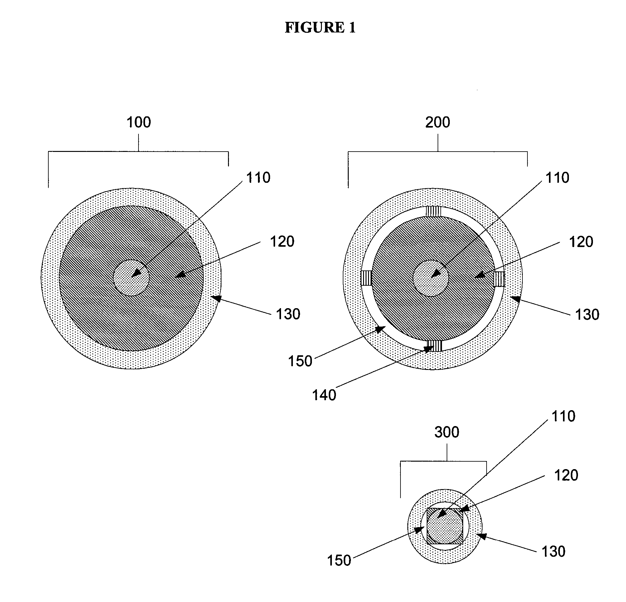
[0033] The present invention relates to systems and devices for delivering energy to tissue for a wide variety of applications, including medical procedures (e.g., tissue ablation, treatment of arrhythmias, cautery, vascular thrombosis, electrosurgery, tissue harvest, etc.). In particular, the present invention relates to systems and devices for the delivery of energy with heat transfer ability. In some embodiments, the systems and devices also have variable characteristic impedance as a result of the use of heat transfer materials. In certain embodiments, methods are provided for treating a tissue region (e.g., a tumor) through application of energy with the systems and devices of the present invention.

[0034] In preferred embodiments, the systems, devices, and methods of the present invention employ microwave energy. The use of microwave energy in the ablation of tissue has numerous advantages. For example, microwaves have a broad field of power density (e.g., approximately 2 cm s...


PUM


Abstract

The present invention relates to systems and devices for delivering energy to tissue for a wide variety of applications, including medical procedures (e.g., tissue ablation, resection, cautery, vascular thrombosis, treatment of cardiac arrhythmias and dysrhythmias, electrosurgery, tissue harvest, etc.). In particular, the present invention relates to systems and devices for the delivery of energy with heat transfer ability. In some embodiments, the systems and devices also have variable characteristic impedance as a result of the use of heat transfer materials. In certain embodiments, methods are provided for treating a tissue region (e.g., a tumor) through application of energy with the systems and devices of the present invention.

Description

[0001] The present application claim priority to U.S. Provisional Application Ser. No. 60 / 785,467, filed Mar. 24, 2007, the entire disclosure of which is herein incorporated by reference in its entirety.FIELD OF THE INVENTION [0002] The present invention relates to systems and devices for delivering energy to tissue for a wide variety of applications, including medical procedures (e.g., tissue ablation, resection, cautery, vascular thrombosis, treatment of cardiac arrhythmias and dysrhythmias, electrosurgery, tissue harvest, etc.). In particular, the present invention relates to systems and devices for the delivery of energy with heat transfer ability. In some embodiments, the systems and devices also have variable characteristic impedance as a result of the use of heat transfer materials. In certain embodiments, methods are provided for treating a tissue region (e.g., a tumor) through application of energy with the systems and devices of the present invention. BACKGROUND [0003] Abl...

Claims


Application Information

Patent Timeline
Patent Type & Authority Applications(United States)
IPC IPC(8): A61B18/18
CPCA61B18/18A61B2018/183A61B2018/00023A61B18/1815
Inventor VAN DER WEIDE, DANIEL W.LEE, FRED T. JR.LAESEKE, PAUL F.BRACE, CHRISTOPHER L.
Owner NEUWAVE MEDICAL
Why Eureka
Try Eureka