Drilling system powered by energy-harvesting sensor

a technology of energy harvesting and energy harvesting, which is applied in the direction of seismology for waterlogging, using reradiation, instruments, etc., can solve the problems of high environmental protection costs, high maintenance costs, and high cost of environmental protection disposal

Active Publication Date: 2008-02-07
SCHLUMBERGER TECH CORP
View PDF9 Cites 31 Cited by
  • Summary
  • Abstract
  • Description
  • Claims
  • Application Information

AI Technical Summary

Benefits of technology

[0029]In the third embodiment, the attribute is temperature difference and the

Problems solved by technology

While mud turbines can provide a large amount of electrical power, they have high maintenance cost.
The use of batteries is also quite expensive due to the amount of space they occupy, along with the associated high costs of environmentally friendly disposal.
Running power cables along the drill string has proven to be impractical and problematic.
Such systems are believed to have suffered from poor reliability and high cost due to of the large number of electrical connectors.
It has never been commercialized for measurement while drilling applications.
This system is believed to have suffered from interference with t

Method used


Image

  • Drilling system powered by energy-harvesting sensor
  • Drilling system powered by energy-harvesting sensor
  • Drilling system powered by energy-harvesting sensor

Examples


first embodiment

, Determining an Attribute of Ambient Energy

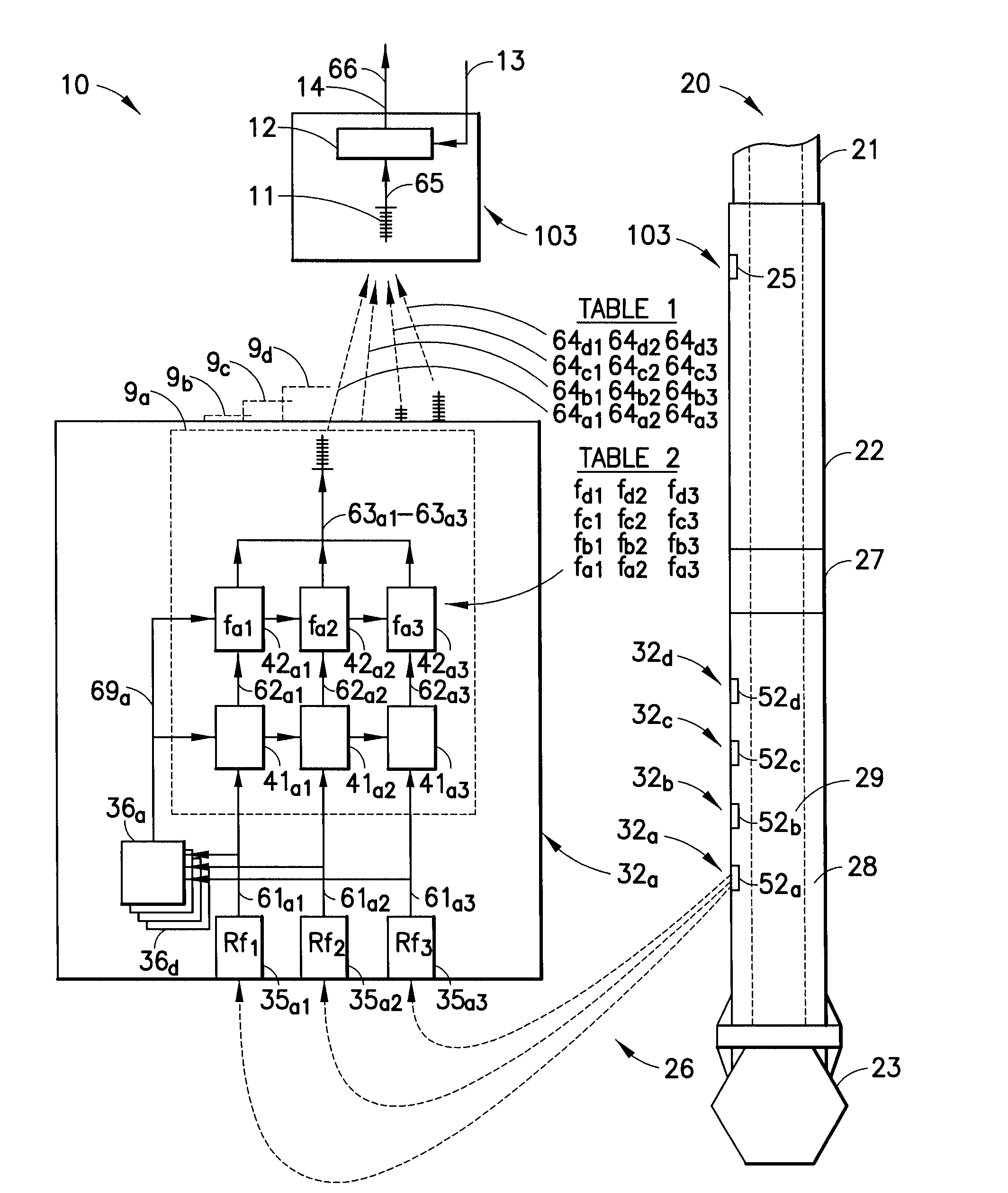
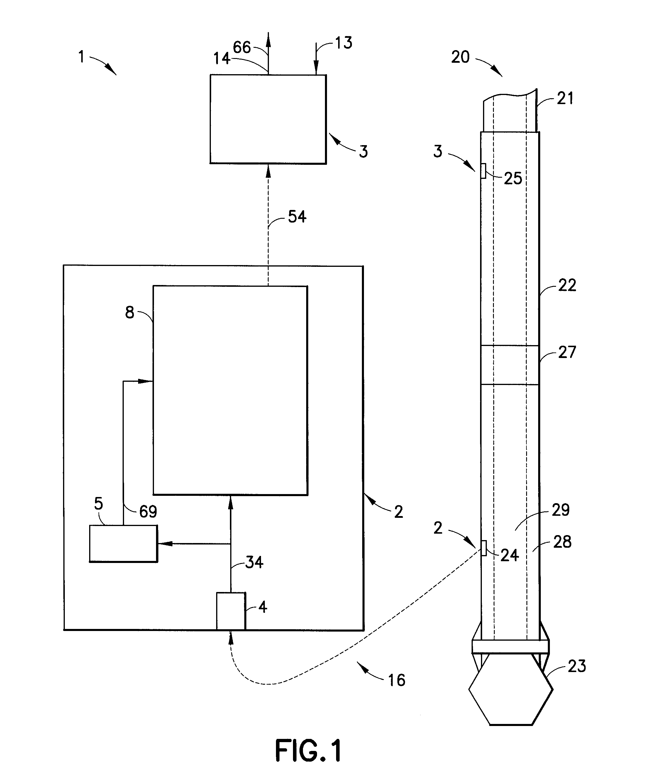
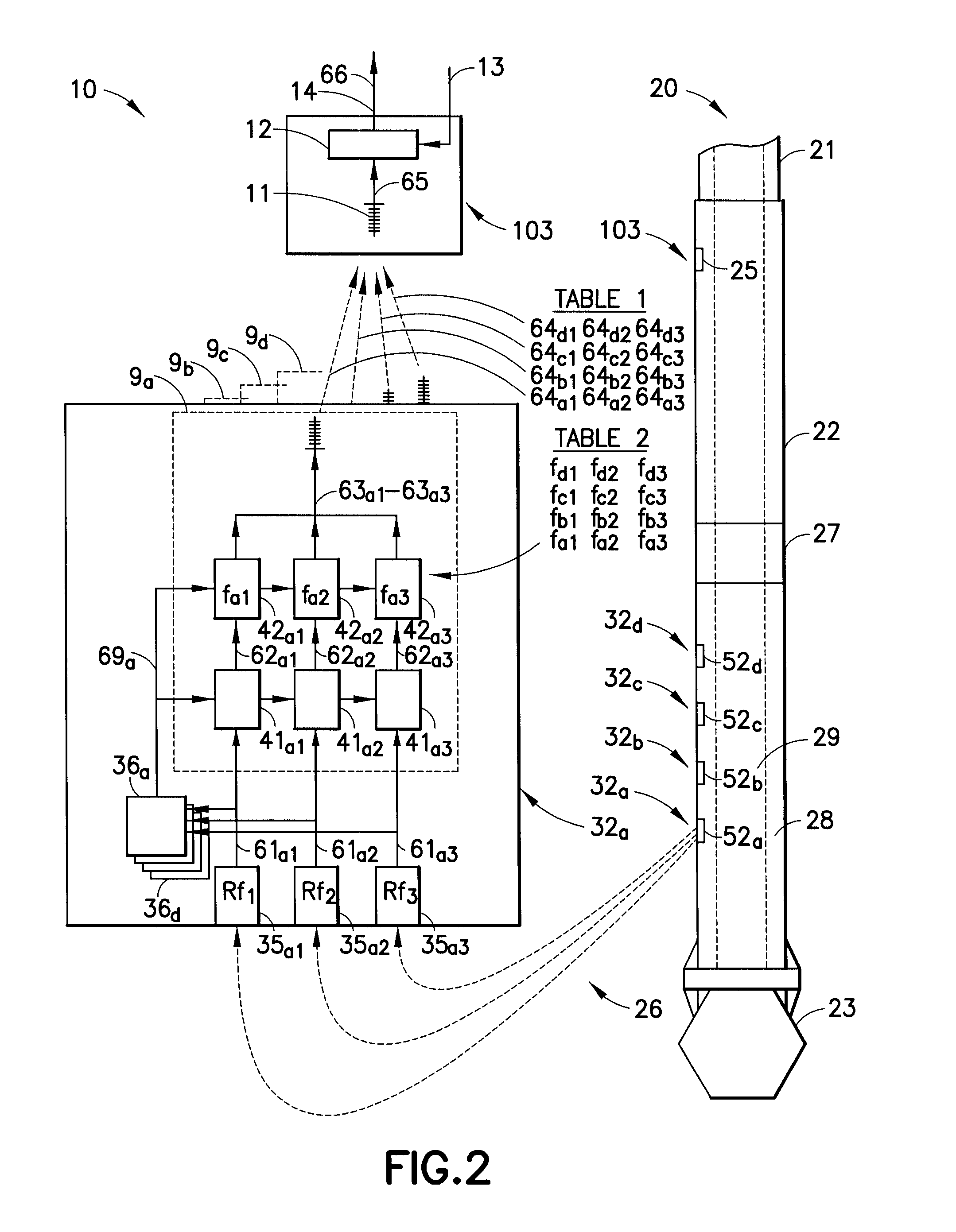
[0043]System 1, shown in FIG. 1, is powered by ambient energy and provides a method for determining the value of an attribute of ambient energy at drilling assembly 22 located at the bottom of a borehole. Attributes include vibration frequency spectrum, pressure difference, and temperature difference. The method of operation is illustrated in the flow chart of FIG. 12.

[0044]In FIG. 1, drill string 20 is shown having drill string tubular 21 that extends up the borehole to the surface station (not shown). Drilling assembly 22 includes drill bit 23 and drilling assembly tubing 28. Drilling assembly tubing 28 defines central aperture 29. Drilling assembly 22 is shown having a barrier 27 representing components that generally preclude the running of electrical wires along the length of the drilling assembly.

[0045]Referring to FIGS. 1 and 12, System 1 operates as follows. Sensor-transmitter station 2 generates first signal 34 and second signal 5...

second embodiment

, Determining Vibration Frequency

[0065]FIG. 3 shows a second embodiment directed to determining vibration frequency. As understood by one skilled in the art, this embodiment is representative of one suitable arrangement for practicing the present invention and is not intended to be limiting in scope.

[0066]System 30 provides a self-powered method for determining the value of vibration energy at a single vibration frequency at a single location on a drilling assembly having no barrier. System 30 uses a single energy-harvesting vibration sensor 35, and transmits a second signal 38 either along a wired connection, or by wireless connection, to the surface station (not shown). As illustrated inFIG. 6, multiple energy-harvesting vibration sensors 35a1-35a2 may be used in practicing the present invention. Each of these energy-harvesting vibration sensors 35a1-35a2 may have a specific resonant frequency (i.e. Rf1, Rf2 Rf3). These individual resonant frequencies are illustrated at FIG. 9 whe...

third embodiment

, Vibration Frequency Spectrum, Wired Transmission

[0069]FIG. 4 shows a third embodiment directed to determining vibration frequency spectrum having wired transmission. The embodiment of FIG. 4 is representative of one suitable arrangement for practicing the present invention. System 30 provides a self-powered method for determining vibration frequency spectrum at a plurality of locations on a drilling assembly. System 30 uses a single energy-harvesting vibration sensor 35, and transmits a second signal 38 either along a wired connection, or directly by wireless connection, to the surface station (not shown). Note that frequency modulation is required but the driver circuits of signal conditioner / multiplexers 87 will differ from the driver circuits of signal conditioner / multiplexers 42 of the first preferred embodiment shown in FIG. 2.

Second Preferred Embodiment, Determining Pressure Difference

[0070]FIG. 10 shows a second preferred embodiment directed to determining pressure differen...


PUM


Abstract

A method and system is provided for determining the value of an attribute of ambient energy at a drilling assembly at the bottom of a borehole. Ambient energy includes kinetic energy, hydraulic energy and thermal energy. Attributes include vibration frequency spectrum, pressure difference, and temperature difference. The method uses energy harvested by at least one energy-harvesting sensor to power the system. The system generates data signals from at least one energy-harvesting sensor at one or more locations along a downhole drilling assembly, and transmits data up the borehole.

Description

TECHNICAL FIELD[0001]The present invention relates to measurements associated with various drilling systems for use in oil well drilling, and for powering the acquisition of measurements, and for powering the transmission of measurement data to a surface station from locations in a borehole.BACKGROUND OF THE INVENTION[0002]Drilling an oil well is typically done with a drill bit attached to a long string of drill pipe, called the drill string. The drill string consists of individual sections of drill pipe, each about 40 ft in length with screw joints at each end. Depending on the geological situation, a drill string can be tens of thousand feet long. The drilling torque is usually transmitted from the drilling rig to the bit through the drill string, whereas the axial thrust force or “weight on bit” is provided by the weight of the drill string itself. In modern drilling operations, a set of highly sophisticated tools that may include formation measurement and bit steering systems ar...

Claims


Application Information

Patent Timeline
IPC IPC(8): G01V1/40
CPCG01V1/44
Inventor PABON, JAHIRGUERRERO, JULIOSIHLER, JOACHIMPAFITIS, DEMOSTHENIS
Owner SCHLUMBERGER TECH CORP
Why Eureka
Try Eureka