Magnetic floating shaft set and apparatus using same

a technology of magnetic floating shaft and set, which is applied in the direction of positive displacement liquid engine, piston pump, liquid fuel engine, etc., can solve the problems of prolonging the working life of the cooling fan and reducing noise level, and achieves long working life, low noise level, and optimal mechanical efficiency.

Inactive Publication Date: 2008-02-14
YU CHIEN CHUN
View PDF3 Cites 9 Cited by
  • Summary
  • Abstract
  • Description
  • Claims
  • Application Information

AI Technical Summary

Benefits of technology

[0008]It is another object of the present invention to provide a magnetic floating shaft set and an apparatus using the magnetic floating shaft set that have the characteristics of optimal mechanical efficiency, long working life, and low noise level.
[0009]To achieve these and other objects of the present invention, the magnetic floating shaft set comprises two guides kept apart from each other at a distance, one of the two guides being movable relative to the other to change the distance between the two guides; a shaft set in between the two guides, the shaft having two distal ends respectively facing the two guides; a magnetic member mounted on the shaft; and a winding coaxially mounted around the shaft and adapted to generate a magnetic field to induce the magnetic member and to further cause floating of the shaft between the two guides and rotation of the magnetic member with the shaft. With the aforesaid arrangement, the magnetic floating shaft set and the apparatus using the magnetic floating shaft set possess a simple structure. Further, the small contact area between the shaft and the guides greatly reduces the friction area, thereby improving the mechanical performance, prolonging the working life of the cooling fan and reducing noise level. Further, the invention allows adjustment of the distance between the two guides, allowing smooth rotation of the magnetic floating shaft set for high speed operation.

Problems solved by technology

Further, the small contact area between the shaft and the guides greatly reduces the friction area, thereby improving the mechanical performance, prolonging the working life of the cooling fan and reducing noise level.

Method used


Image

  • Magnetic floating shaft set and apparatus using same
  • Magnetic floating shaft set and apparatus using same
  • Magnetic floating shaft set and apparatus using same

Examples


Embodiment Construction

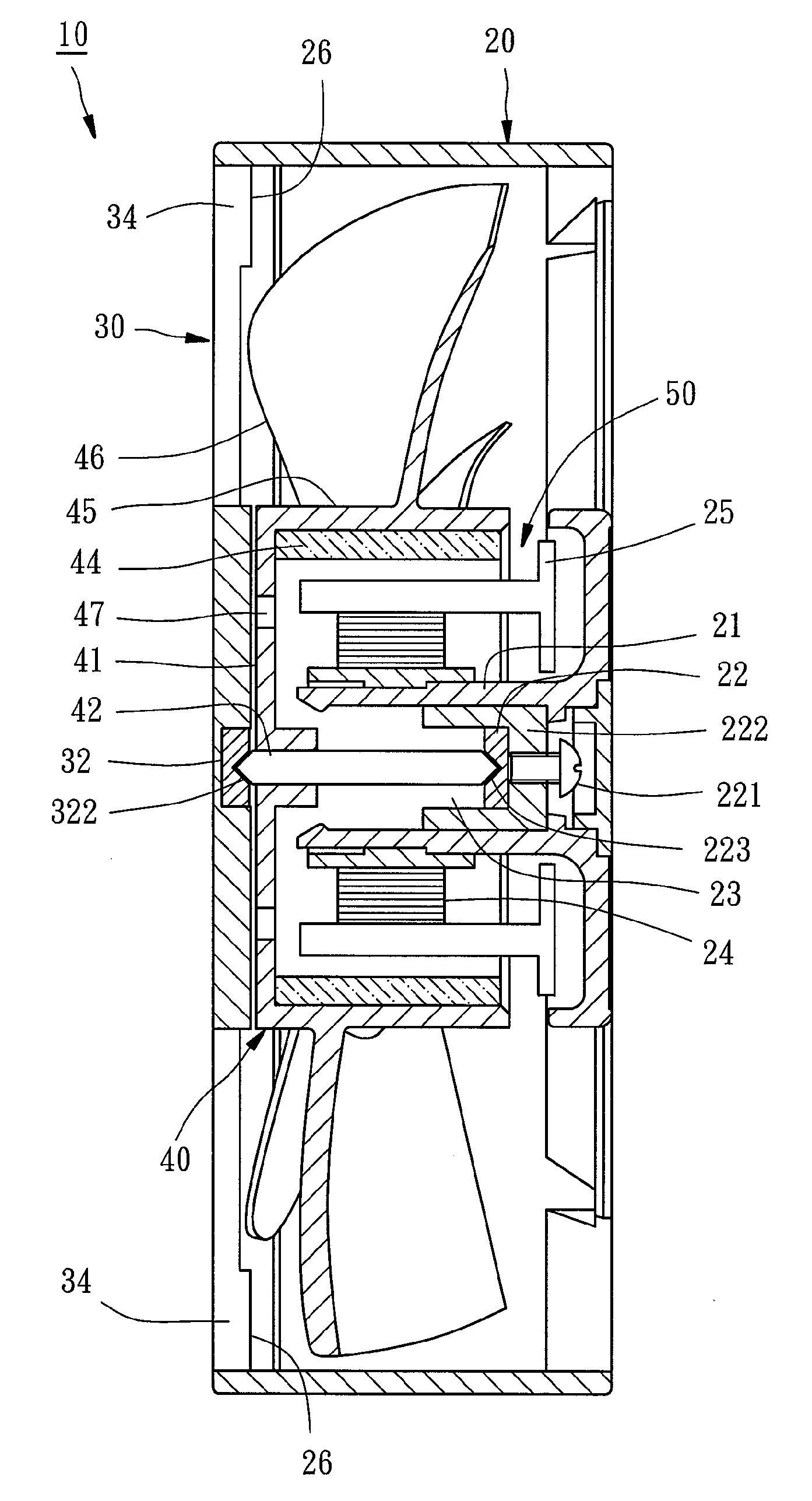
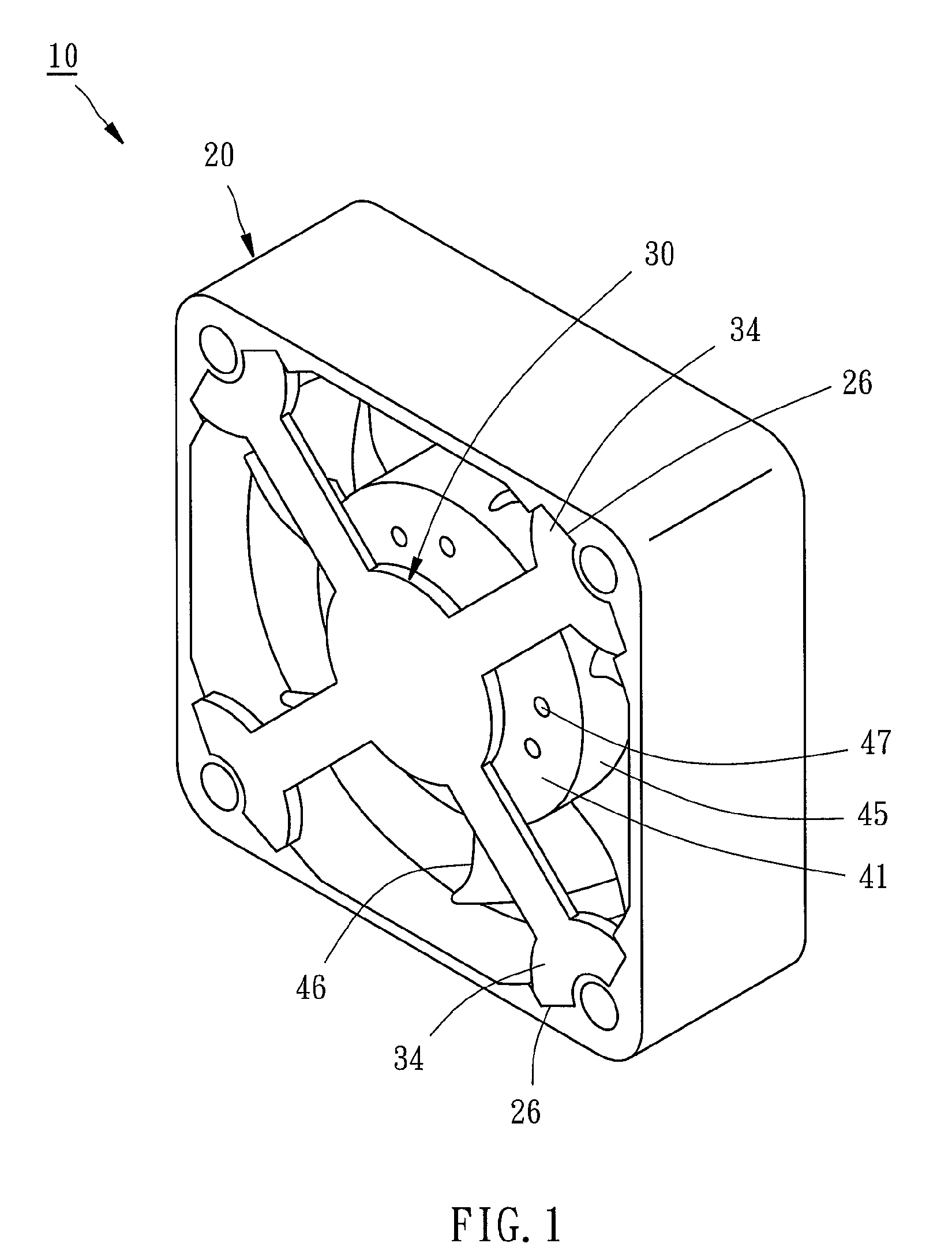
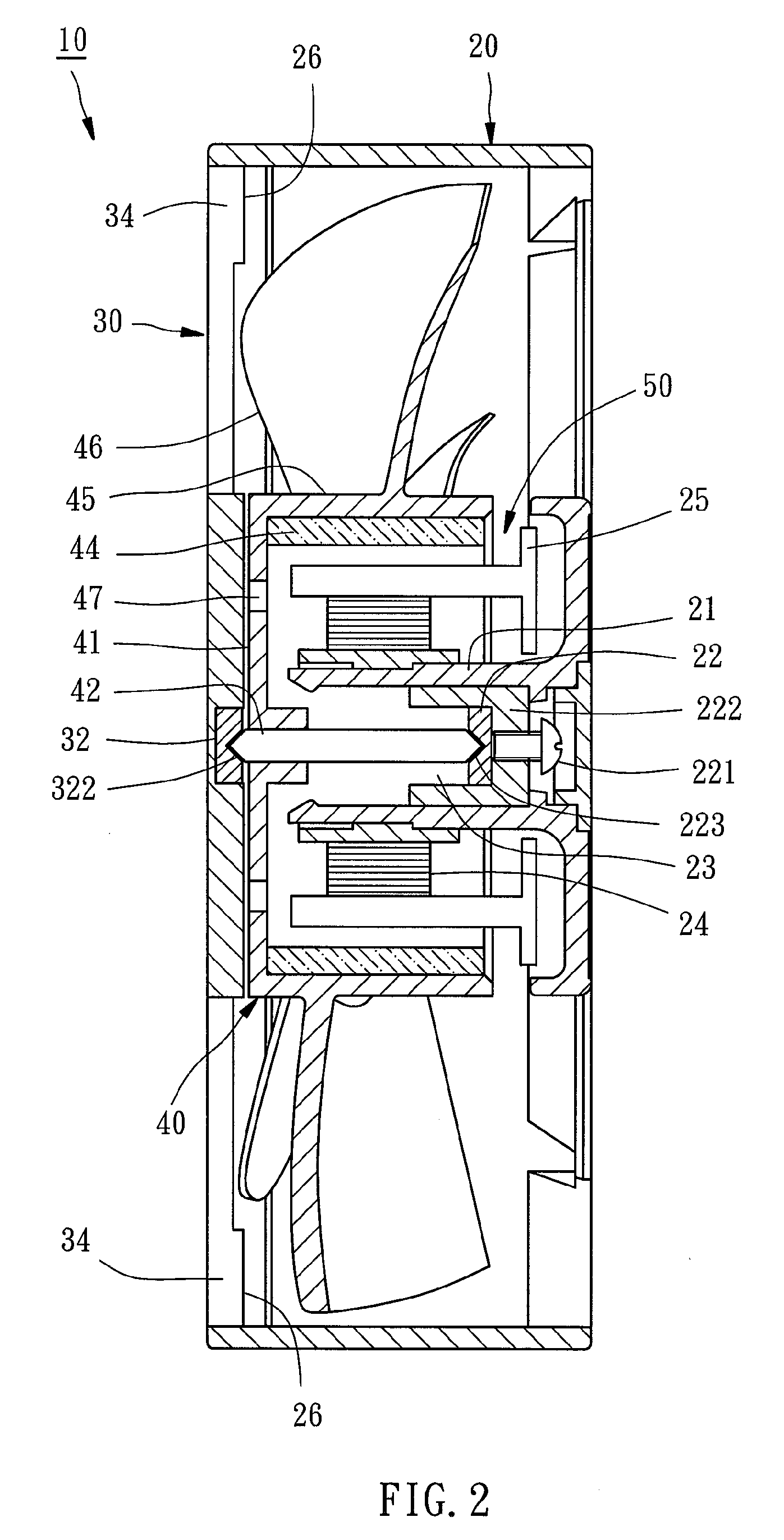
[0026]Referring to FIGS. 1˜3, a magnetic floating shaft set 50 in accordance with a first embodiment of the present invention is shown used in a cooling fan 10. The cooling fan 10 comprises a first rack 20 and a second rack 30. The magnetic floating shaft set 50 is mounted in between the first rack 20 and the second rack 30.

[0027]The first rack 20 has four limit portions 26 at one side. The limit portions 26 are respectively formed in the corners of the rack 20. The second rack 30 has four locating portions 34. The locating portions 34 are respectively engaged into the limit portions 26 to secure the second rack 30 to the first rack 20.

[0028]As illustrated in FIG. 2, the first rack 20 has a hollow center portion 21 that accommodates a positioning member 222. The positioning member 222 has an insertion hole 23. The positioning member 222 is mounted with an adjustment member 221. According to this embodiment, the adjustment member 221 is a screw. The adjustment member 221 is screwed i...


PUM


Abstract

A magnetic floating shaft set is disclosed to include two guides kept apart from each other at a distance in such a manner that one guide is movable relative to the other guide to adjust the distance between the two guides, a shaft set in between the two guides with the two distal ends thereof respectively facing the two guides, a magnetic member mounted on the shaft, and a winding coaxially mounted around the shaft for generating a magnetic field to induce the magnetic member and to further cause floating of the shaft between the two guides and rotation of the magnetic member on the shaft.

Description

BACKGROUND OF THE INVENTION[0001]1. Field of the Invention The present invention relates to magnetic floating shafts and more particularly to a magnetic floating shaft set for high speed rotation.[0002]2. Description of the Related Art[0003]Cooling fan is intensively used in different fields to cause currents of air for cooling or dissipation of heat. FIG. 16 shows a conventional cooling fan 1. As illustrated, the cooling fan 1 comprises a stator 2 and a rotor 3. The stator 2 comprises an axle bearing 4, a winding 5 arranged around the axle bearing 4. The rotor 3 has a shaft 6, a magnetic ring 7, and a plurality of blades 8. The shaft 6 is inserted through the axle bearing 4. The blades 8 are radially connected to the shaft 6. During operation of the cooling fan 1, the interaction between the magnetic ring 7 and the winding 5, causes the shaft 6 to rotate. During rotation of the shaft 6, the blades 8 are moved with the shaft 6 to cause currents of air.[0004]During operation of the a...

Claims


Application Information

Patent Timeline
Patent Type & Authority Applications(United States)
IPC IPC(8): H02K7/09F04B17/00
CPCF04D29/0467F04D29/058H02K7/083F16C32/04H02K7/09F04D25/062H02K7/086F16C2360/46
Inventor YU, CHIEN-CHUN
Owner YU CHIEN CHUN
Why Eureka
Try Eureka