Stage apparatus and exposure apparatus

Inactive Publication Date: 2008-02-14
NIKON CORP
View PDF17 Cites 1 Cited by
  • Summary
  • Abstract
  • Description
  • Claims
  • Application Information

AI Technical Summary

Benefits of technology

[0015] According to the third aspect of the present invention, it is possible to reduce the weight of the mirror while maintaining

Problems solved by technology

When for example moving members in the stage system are made thin in order to lighten the stage system,

Method used


Image

  • Stage apparatus and exposure apparatus
  • Stage apparatus and exposure apparatus
  • Stage apparatus and exposure apparatus

Examples


Embodiment Construction

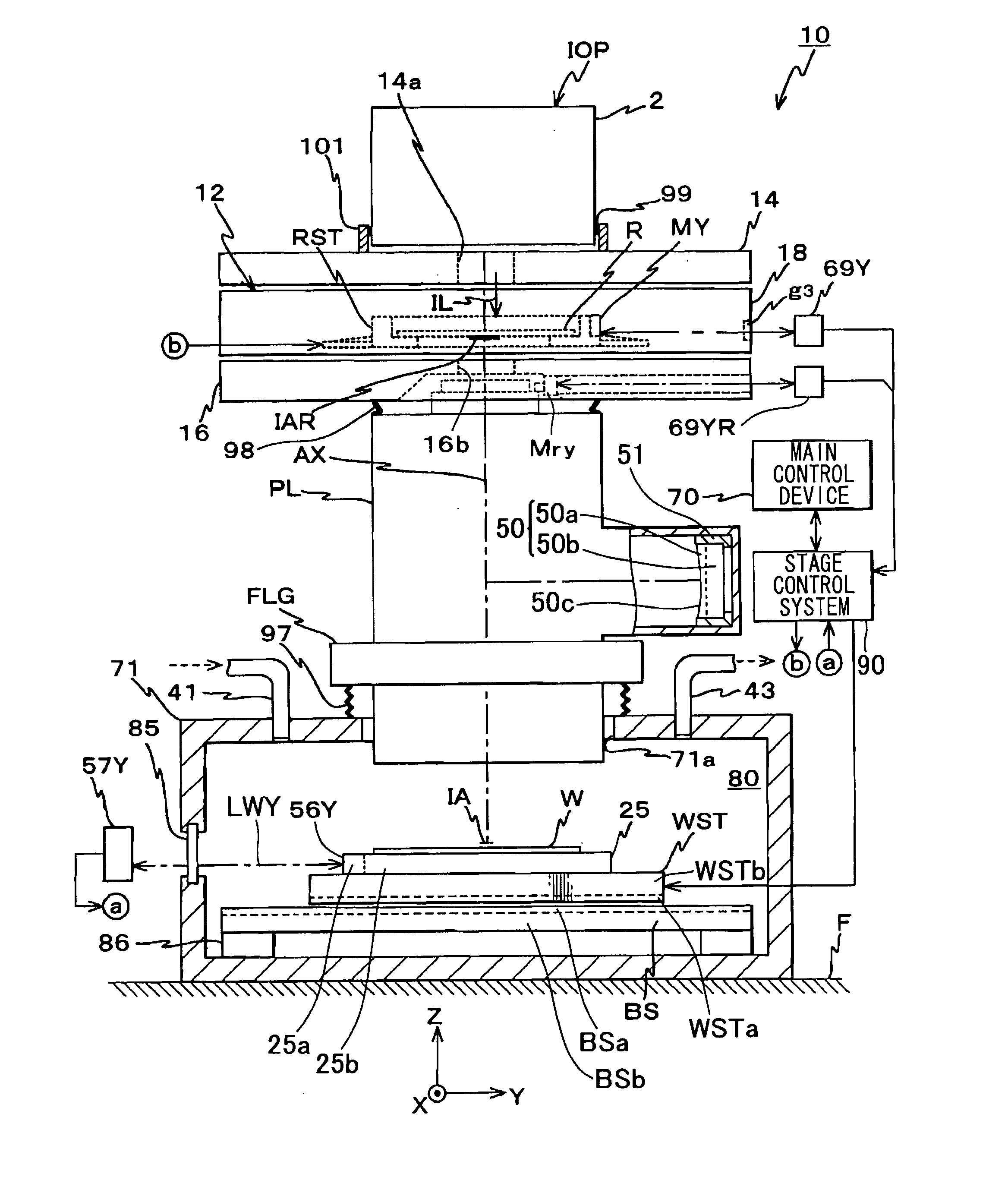
[0025] An example of a preferred embodiment of the present invention shall be described hereinbelow with reference to the drawings. The present embodiment is one in which the present invention is applied to a scanning exposure-type projection exposure apparatus (exposure apparatus) known as a scanning stepper.

[0026]FIG. 1 shows the schematic configuration of a projection exposure apparatus 10 of the present embodiment. In FIG. 1, the Z axis is taken that is perpendicular to the object surface (which is parallel to the image plane) of a projection optical system PL that is provided in the projection exposure apparatus 10; the Y axis is taken in the scanning direction of a reticle R and a wafer W during scanning exposure in the plane that is perpendicular to the Z axis; and the X axis is taken in the non-scanning direction perpendicular to the scanning direction (the direction perpendicular to the page in FIG. 1).

[0027] The projection exposure apparatus 10 of the present embodiment ...


PUM


Abstract

A wafer stage system moves a wafer stage that retains a wafer via a wafer holder along a wafer base. For example, the wafer holder is formed from a material whose density is not uniform, such that the portion that includes the reflecting surface that reflects a measuring beam for position measurement is a high-density portion, and the other portions are low-density portions. Or, the wafer stage is formed from a material whose density is not uniform, such that the portion that includes the surface that constitutes a gas bearing is a high-density portion, and the other portions are low-density portions.

Description

CROSS-REFERENCE TO RELATED APPLICATION [0001] The present application claims priority on Japanese Patent Application No. 2006-194890, filed Jul. 14, 2006, the content of which is incorporated herein by reference. BACKGROUND [0002] 1. Field of the Invention [0003] The present invention relates to a stage apparatus for driving an object, being suitably used for a stage system of an exposure apparatus that is used for transferring a mask pattern onto a substrate in a photolithography process for manufacturing devices such as semiconductor elements, imaging elements, liquid-crystal display elements, or thin-film magnetic heads and the like. [0004] 2. Related Art [0005] In a photolithography process for manufacturing devices such as semiconductor elements or liquid-crystal display elements (electronic devices, micro-devices, and the like), in order to project and expose via a projection optical system a circuit pattern formed on a reticle (or photomask) onto a wafer (or glass plate etc.)...

Claims


Application Information

Patent Timeline
IPC IPC(8): G03B27/54G03B27/58
CPCH01L21/682G03F7/70716G03F7/7015G03F7/70233G03F7/70725G03F7/70758
Inventor SHIBAZAKI, YUICHI
Owner NIKON CORP
Why Eureka
Try Eureka