Underwater acoustic positioning system and method

a positioning system and underwater technology, applied in direction finders, direction finders using ultrasonic/sonic/infrasonic waves, instruments, etc., can solve the problems of limiting the amount of dtls that can participate in the scheme, increasing the complexity and power consumption of the dtls system, and the radio-based system cannot be directly used underwater. , to achieve the effect of improving the reliability of positioning systems and methods, reducing the acoustic bandwidth, and reducing the cost of

Active Publication Date: 2008-02-14
L3 TECH INC
View PDF12 Cites 45 Cited by
  • Summary
  • Abstract
  • Description
  • Claims
  • Application Information

AI Technical Summary

Benefits of technology

[0019] The present invention provides a significant advantage over the prior art systems in that it can use very little acoustic bandwidth and the amount of data is fixed for any number of devices to locate. In the present invention, the signal from each buoy arrives at a known time and has predetermined data (for example, an acoustic ping at a known frequency and duration). The signal is very easy to detect in noisy environments and it leaves most of the underwater acoustic channel available for other uses such as acoustic data modems. In addition, by calculating acoustic attenuation of the locating signals based on distance and

Problems solved by technology

However, since radio waves at the frequency of GPS attenuate very quickly in seawater, the radio-based system cannot be directly used underwater.
The LBL system works very well, but requires that both the buoys and DTLs transmit data increasing the amount of acoustic bandwidth requires as the number of DTLs are increased, limiting the amount of DTLs that can participate in the scheme.
The complexity and power consumption of the DTLs system is increased significantly as it must also transmit data to the buoys.
The SBL system suffers the same problems as the LBL system, namely; required underwater bandwidth increases linearly as you add more devices to locate, increased complexity of DTL hardware/software and very difficult setup of the system.
A disadvantage of this scheme is that it relies on receiving some very long messages in the noisy underwater environment.
Th

Method used


Image

  • Underwater acoustic positioning system and method
  • Underwater acoustic positioning system and method
  • Underwater acoustic positioning system and method

Examples


Embodiment Construction

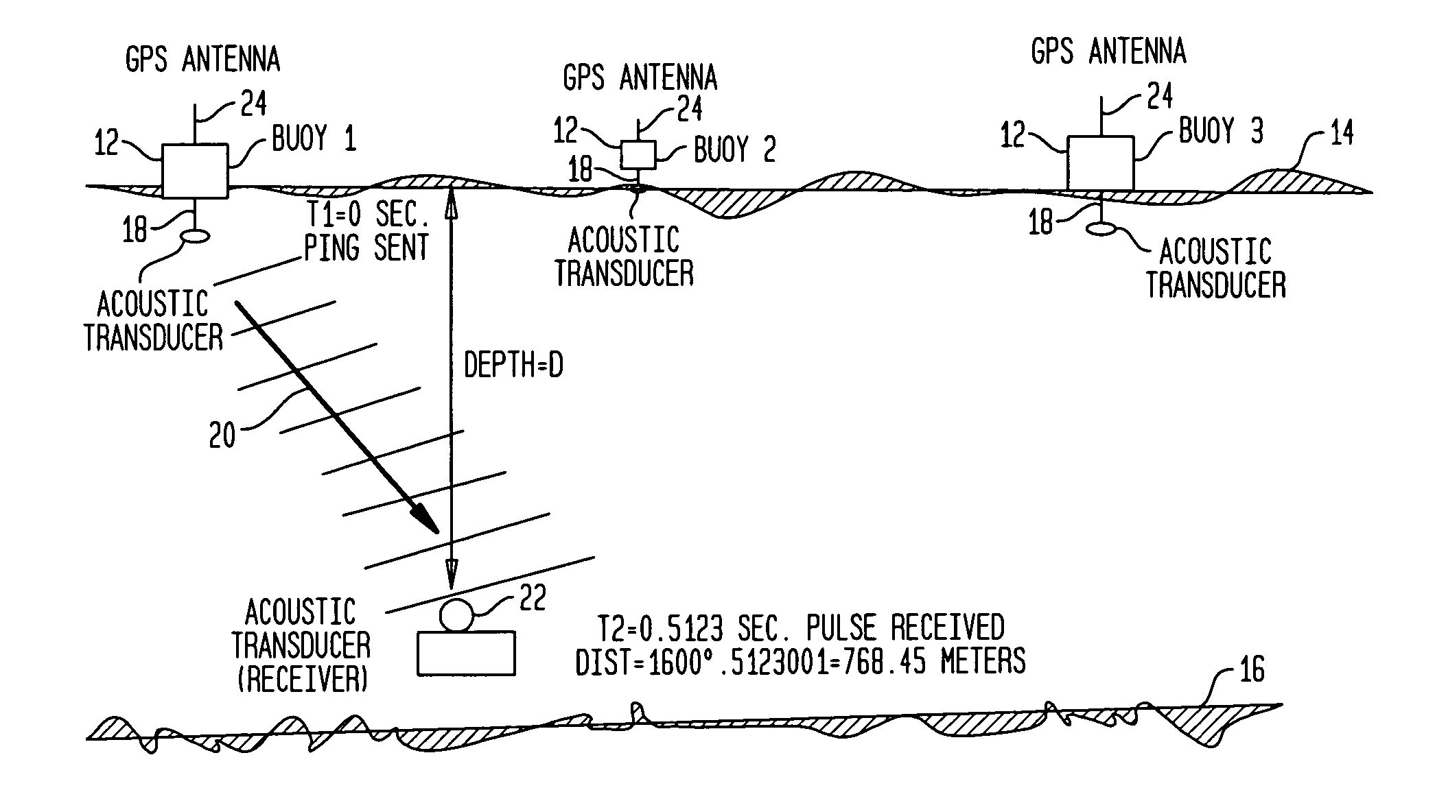
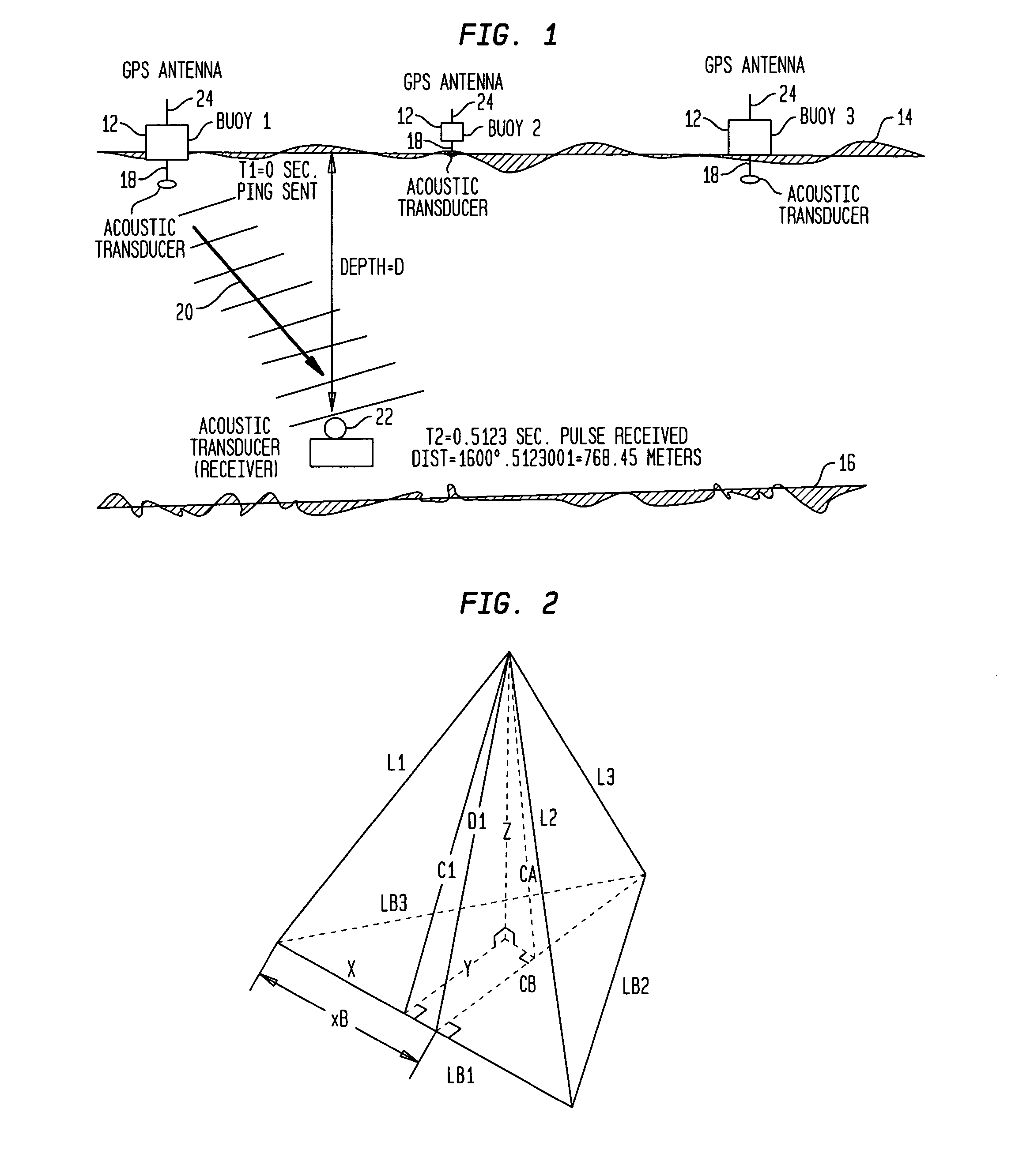
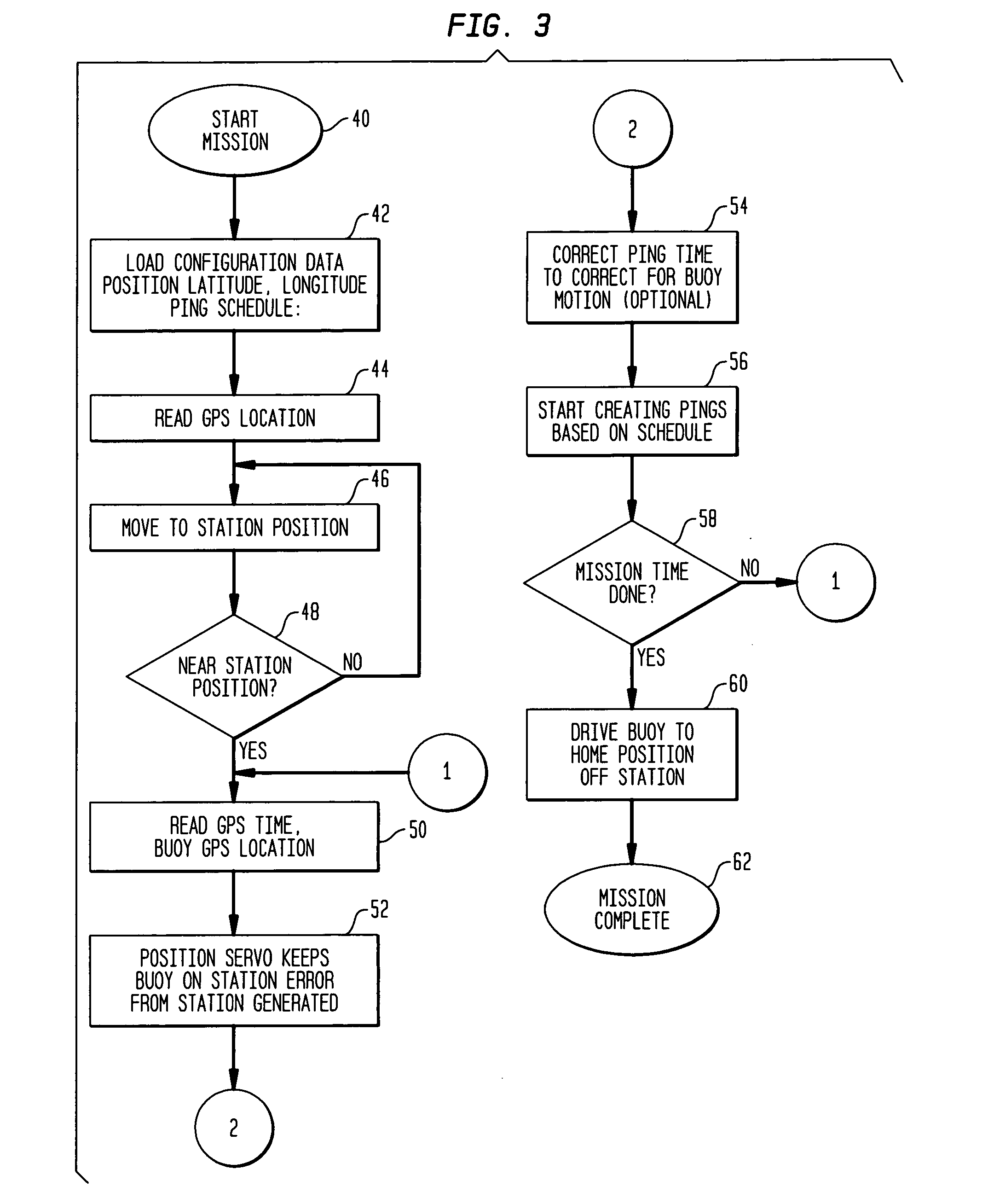
[0030] The present invention provides a method and apparatus for locating an accurate 3-dimensional position of an underwater device or vehicle using an acoustic signaling method and a stabilized time base. The stabilized time base can be provided on the device to locate using a stabilized clock. If the depth of the device to locate (DTL) is known, the system requires at least two spatially separated acoustic transmitters (buoys) in fixed locations on the surface of the water. These buoys are referred to as station keeping buoys. An alternative scheme would allow the buoys to be fixed underwater at a known location, not subject to the position error when they are floating, the time base for such a station keeping buoy could be provided by a floating GPS receiver on a cable (GPS time would only be available through the cable) or a stabilized clock such as used in the DTLs. The time on the buoys could also be updated by cable, by coming to the surface from time to time, or some other ...


PUM


Abstract

A method for determining the position of an underwater device includes placement of a plurality of station keeping devices on or below the surface of the water in known positions. A device to locate is provided for placement below the surface of the water, and the device to locate and the station keeping devices are provided with a synchronized time base and a common acoustic pulse time schedule. Each station keeping device sends an acoustic pulse at a time according to the common acoustic pulse schedule. The device to locate receives pulses sent by the station keeping devices and calculates a distance between itself and each station keeping device based upon the time that the acoustic pulse is sent and the time that the pulse is received. The device to locate then calculates its position based upon the distances between the device to locate and the station keeping devices. Systems and devices are also disclosed.

Description

RELATED APPLICATIONS [0001] This application claims priority to U.S. Provisional Patent Application No. 60 / 708,741, filed on Aug. 16, 2005, and entitled “Underwater Acoustic Positioning System,” which patent application is hereby incorporated by reference in its entirety.FIELD OF THE INVENTION [0002] The invention relates to systems for locating the position of an object and, in particular, to an acoustic system for locating the position of an object located underwater. BACKGROUND [0003] A system that accurately determines the position of an underwater device would be highly useful for a number of underwater activities. GPS can provide very accurate position location information on the surface of the globe. GPS refers to the Global Positioning System, a constellation of more than two dozen GPS satellites that broadcast precise timing signals by radio to electronic GPS receivers which allow them to accurately determine their location (longitude, latitude, and altitude) in real time. ...

Claims


Application Information

Patent Timeline
IPC IPC(8): G01S3/80
CPCH04B11/00G01S5/30
Inventor CROWELL, JONATHAN C.
Owner L3 TECH INC
Why Eureka
Try Eureka