Wave Energy Harvesting and Hydrogen-Oxygen Generation Systems and Methods

a technology of hydrogen-oxygen generation and wave energy, applied in the direction of special-purpose vessels, vessel parts, vessel construction, etc., can solve the problems of incongruous wind conditions, increased site limitations for harvesting energy, high land costs and potential political resistance, etc., to maximize kilowatt revenue per kilowatt, minimize moving parts, and maximize kilowatt production per unit

Active Publication Date: 2008-02-14
RUSSO MICHAEL L
View PDF36 Cites 34 Cited by
  • Summary
  • Abstract
  • Description
  • Claims
  • Application Information

AI Technical Summary

Benefits of technology

[0037]An underlying object of embodiments of the invention is to maximize revenue per kilowatt and to maximize kilowatt production per unit.
[0038]A more detailed object of embodiments of the invention is to minimize moving parts thereby to create a robust and durable arrangement.
[0039]Still other objects of embodiments of the invention are to provide systems and methods for gas storage, gas liquefaction, and transfer and distribution with enhanced communication and control capabilities and minimized operational labor costs.
[0042]In certain embodiments, multiple bobber devices can be disposed in series to establish a column of bobber devices. With the bobber devices disposed in a column, energy can be sequentially harvested from an oncoming wave with each succeeding bobber device extracting a further percentage of the total energy available in the wave. To facilitate the ability of the bobber devices to harvest energy, the vessel can include one or more wave channels with an open volume defined by first and second sides for enabling a channeled passage of portions of oncoming waves. In each wave channel, a column of bobber devices can be disposed with the float heads of the bobber devices positioned to reciprocate in the open volume of the wave channel. Embodiments of the vessel can have multiple hulls, and the sides of adjacent hulls can together define a wave channel.
[0046]The vessel can further incorporate an electrolyzer, which can receive electricity generated by the conversion arrangement and which can receive water from a source of water in fluidic communication with the electrolyzer. With this, the bobber devices can produce electricity to power an electrolysis process thereby to enable a separation of water supplied to the electrolyzer into hydrogen and oxygen. The electrolyzer can be a high pressure electrolyzer operative at pressures of 3,000 psi or greater, and, in certain embodiments, the source of water can be a reverse osmosis (RO) water purification system for providing purified water from seawater. Storage containers in fluidic communication with the electrolyzer can enable storage of hydrogen and oxygen produced by the electrolyzer.

Problems solved by technology

As the terrain changes from hills and mountains on the west coast to flat lands across the Great Plains and back to hills on the east coast, winds at high levels periodically dip down into low-lying areas causing inconsistent wind conditions.
These factors translate into increasingly significant site limitations for harvesting energy the farther eastward across the country one looks.
Such sites are often unavoidably located in populated areas thereby being subject to high land costs and potential political resistance.
Consequently, they are limited by, among other things, site limitations, the cost of ocean front property, and political issues such that enjoying profitability relative to traditional wave power systems is a challenge at best.
In addition, since the best quality and most consistent wave activity occurs miles off shore, shore or near-shore sites with acceptable wave activity are relatively rare while acceptable deep ocean sites are almost unlimited.
Furthermore, since the horizon is about 20 to 25 miles from land, offshore wave vessels beyond the horizon would not be visible from land thereby limiting or entirely obviating opposition.
A major drawback with such projects is that they rely on land-based wind turbine technology in on-shore or marginally offshore applications.
In addition, since they are close to land, such applications are impacted by the land effect conditions discussed above thereby further negatively affecting annual returns on investment.
Still further, these systems are anchored directly to the ocean bottom and, therefore, require shallow ocean depths.
Yet another limitation on current wind farms is that they must be physically close to their demand to minimize transmission line losses.
Consequently, most regions have a dearth of acceptable locations for wind energy generation.
Nonetheless, operating in open water presents challenges.
Exposure to harsh conditions demands that equipment be rugged and transportable to resist and avoid damage from storms and other sources.
However, long distance water travel can be costly if not controlled.
Furthermore, the potential for loss of communication requires robust backup systems and procedures.
Also, bottom conditions may cause wave heights to vary widely from the numbers established by Beaufort.

Method used


Image

  • Wave Energy Harvesting and Hydrogen-Oxygen Generation Systems and Methods
  • Wave Energy Harvesting and Hydrogen-Oxygen Generation Systems and Methods
  • Wave Energy Harvesting and Hydrogen-Oxygen Generation Systems and Methods

Examples


Embodiment Construction

[0075]It will be appreciated that the wave energy harvesting and hydrogen-oxygen generation systems and methods disclosed herein are subject to widely varied embodiments. However, to ensure that one skilled in the art will be able to understand and, in appropriate cases, practice the present invention, certain preferred embodiments of the broader invention revealed herein are described below and shown in the accompanying drawing figures. Before any particular embodiment, of the invention is explained in detail, it must be made clear that the following details of construction, descriptions of geometry, and illustrations of inventive concepts are mere examples of the many possible manifestations of the invention.

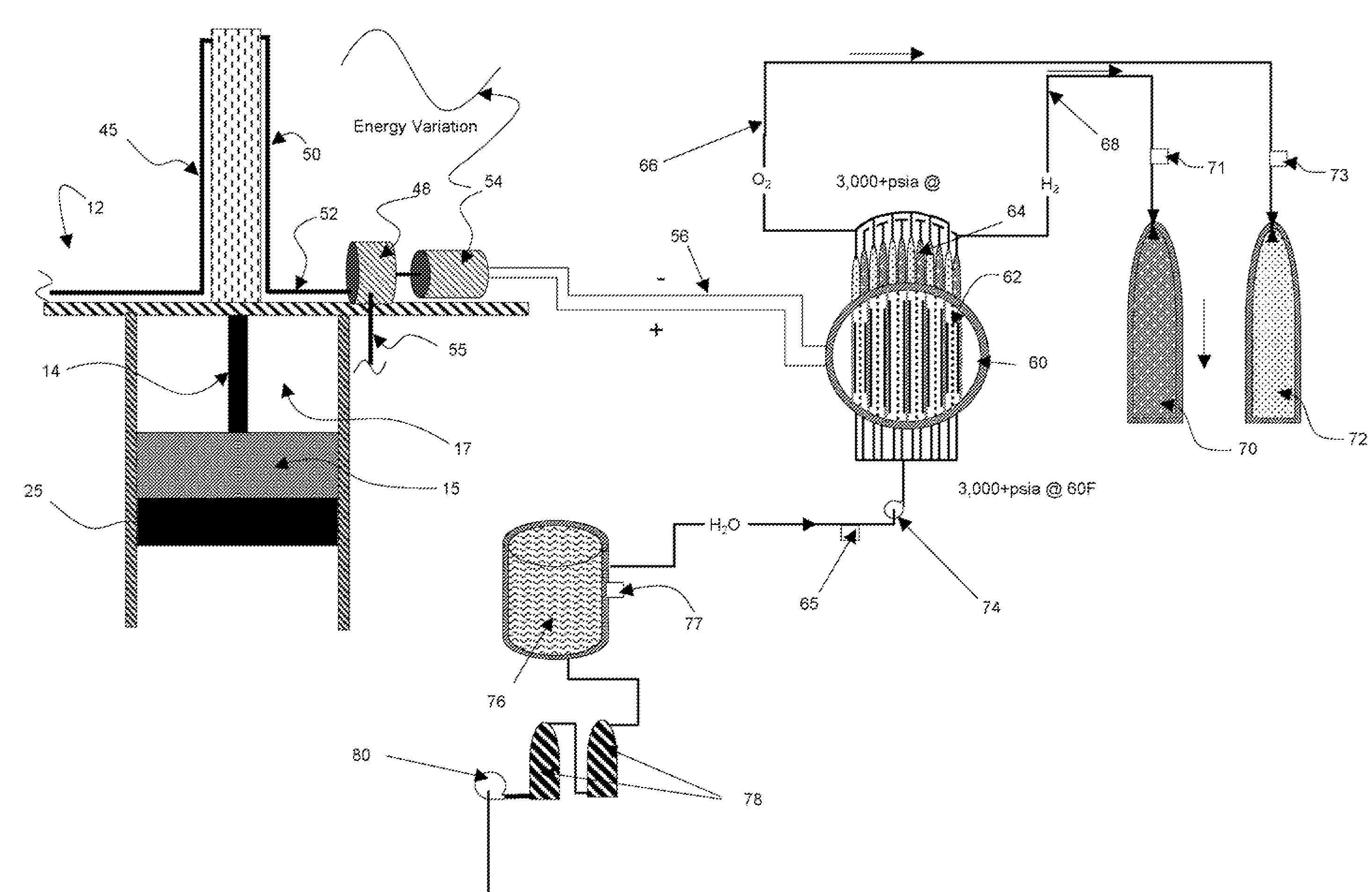
[0076]The wave energy conversion concept can be better understood by reference to FIG. 8. There, the vertical action of waves 200 drive a bobber flotation device 12 vertically. The force of the vertical motion can be assumed to be approximately equal to the volume of water dis...


PUM


Abstract

A system for harvesting energy from wave oscillation includes an energy harvesting vessel and, possibly, a transport vessel. The energy harvesting vessel can have multiple hulls disposed in parallel with wave channels therebetween for receiving incoming waves. Multiple bobber devices can be disposed in series within each wave channel to absorb energy from incoming waves. Reciprocating movement of buoyant float heads of the bobber devices can be converted to electrical energy by a hydraulic engine and a generator. The electrical energy can power an electrolyzer to separate supplied water into hydrogen and oxygen. Once harvested, the hydrogen and oxygen can be transferred between storage tanks on the energy harvesting vessel and the transport vessel for transport and usage. A horizontal movement sea anchor can resist undesired horizontal movement, and a vertical movement sea anchor can resist undesired vertical movement.

Description

RELATED APPLICATIONS[0001]This application is related to U.S. Pat. No. 6,918,350, issued Jul. 19, 2005; application Ser. No. 11 / 105,980, filed Apr. 14, 2005; Application No. 60 / 823,276, filed Aug. 23, 2006; and Application No. 60 / 791,972, filed Apr. 13, 2006, the disclosures of the same being expressly incorporated herein by reference.FIELD OF THE INVENTION[0002]The present invention relates generally to systems and methods for energy conversion More particularly, disclosed herein are water-body applied systems and methods for harvesting wave energy and, in certain embodiments, for employing that energy to produce hydrogen and oxygen through electrolysis.BACKGROUND OF THE INVENTION[0003]Trade winds travel from west to east across the United States and onto the Atlantic Ocean. As wind comes in contact with the land on the west coast, the land absorbs energy from the wind at low altitudes. As the terrain changes from hills and mountains on the west coast to flat lands across the Great...

Claims


Application Information

Patent Timeline
Patent Type & Authority Applications(United States)
IPC IPC(8): E02B9/08
CPCB63B35/00B63B2035/4466Y02E10/28F05B2240/95Y02E10/20F03B17/025Y02E10/30
Inventor MORSE, ARTHUR P.
Owner RUSSO MICHAEL L
Why Eureka
Try Eureka