Management and control of multi-layer networks

a multi-layer network and network management technology, applied in the field of management and controlling a communications network, can solve the problems of limiting the potential revenue return of the network operator, the difficulty of human intervention in providing the network management function, etc., to achieve efficient resource utilization, minimise the number of refusals for admission, and maximise the revenue return of the operator

Inactive Publication Date: 2007-09-11
RPX CLEARINGHOUSE
View PDF18 Cites 63 Cited by
  • Summary
  • Abstract
  • Description
  • Claims
  • Application Information

AI Technical Summary

Benefits of technology

[0025]The arrangement and method provide a seamless merging of automatic management and control processes to provide an efficient utilisation of resources for the various network layer and thus provides a means of maximising a revenue return to an operator of the network.
[0026]The arrangement effectively provides an internal market within the network from which resources are offered to customers at a prevailing price. This minimises the number of refusals for admission to the network under busy conditions as a customer can be permitted access if he / she is prepared to pay the current premium for admission.

Problems solved by technology

An increasing problem with such networks is that of management in order to allocate network resources, particularly bandwidth, in a manner which ensures efficient resource utilisation and maximises the revenue return to the network operator(s).
With the increasing complexity of communications networks and the increasing variety of services that is being introduced, the use of human intervention to provide the network management function is becoming increasingly difficult, particularly with regard to the issue of revenue maximisation.
A further problem that has been experienced with multi-layer networks is that of congestion management Congestion in any of the network layers can severely restrict the traffic handling capacity and thus limit the potential revenue return for the network operator.

Method used


Image

  • Management and control of multi-layer networks
  • Management and control of multi-layer networks
  • Management and control of multi-layer networks

Examples


Embodiment Construction

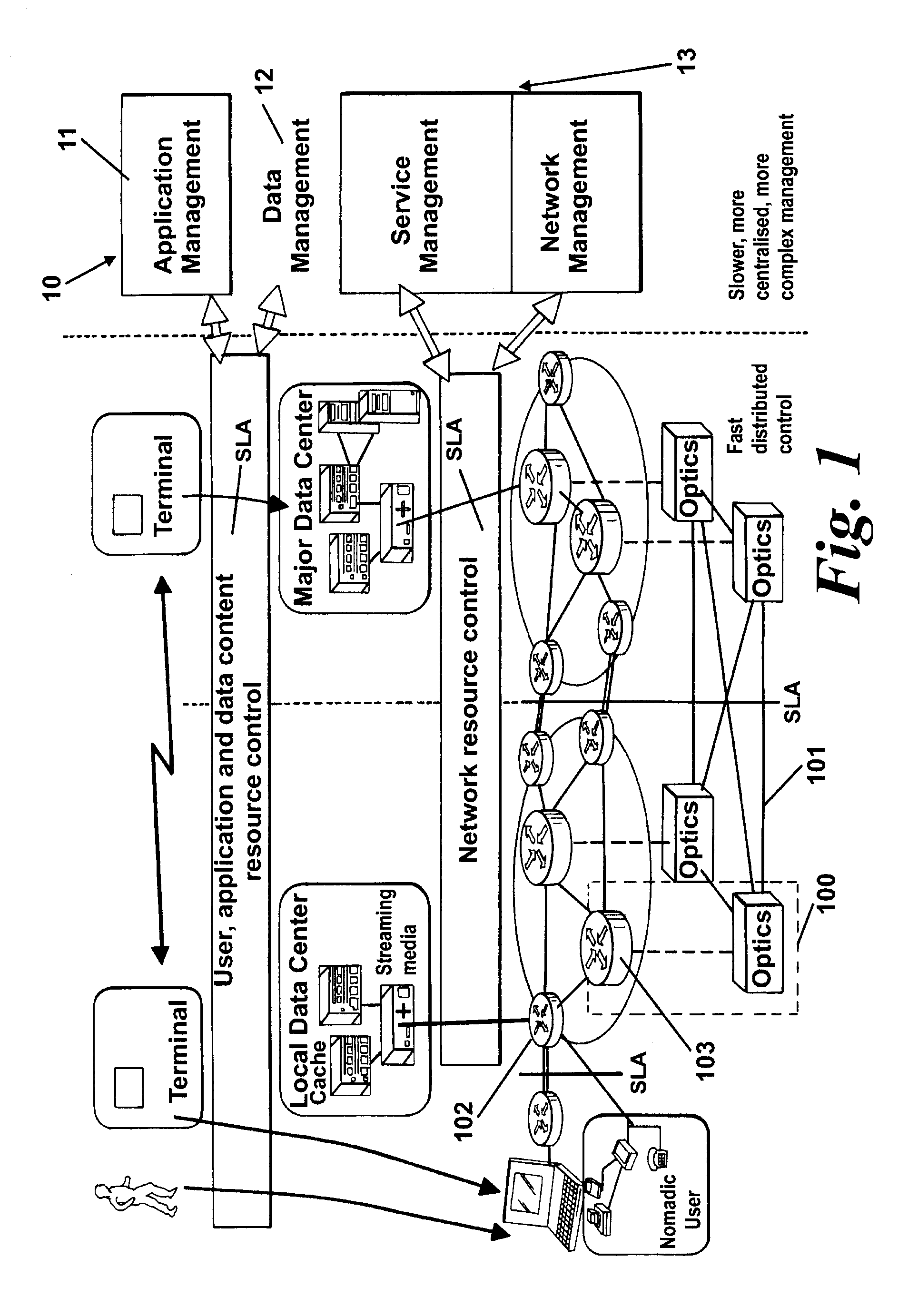
[0049]Referring first to FIG. 1, this shows in schematic form a high level view of the architecture of the network management and control systems. The management system 10 depicted in FIG. 1 is hierarchical with high level application (11) and data (12) management services built upon lower level transport services (13) which in turn are provided by network and link level transmission services. For scalability and response speed it is desirable that the high speed control aspects are physically distributed across the network, whilst more longer term management aspects can be more centrally monitored and managed. User access is provided via terminals 15.

[0050]The network of FIG. 1 incorporates an underlying optical transport or lambda switched layer 101 supporting a network of nodes 102 and core nodes 103. It will be understood that the optical transport layer may carry traffic on a plurality of optical wavelengths in a wavelength division multiplex (WDM) arrangement. The structure of...


PUM


Abstract

A communications network has multiple resource-allocation layers and incorporates a management structure for allocating resources to allocate resources requested by a first layer of said layers from a second of said layers. At a first layer, the management structure provides an indication to a second layer of the required resources that are to be allocated from the second layer. The second layer automatically offers the required resource together with a condition for use of those resources. This condition includes a notional price factor which is dependent on current demand. Under the control of the manager, the first layer determines if the condition for use of the offered resources is acceptable and, if so, automatically accepts the offered resources from the second layer. In a preferred embodiment, ingress to an underlying multi-wavelength transport layer of the network is controlled via a virtual port which allocates traffic to real ports one for each wavelength supported by the transport layer.

Description

RELATED APPLICATIONS[0001]This application is the non-provisional filing of Provisional Application No. 60 / 206,078 filed on May 22, 2000.FIELD OF THE INVENTION[0002]The present invention relates to a method and apparatus for managing and controlling a communications network and to a network incorporating such apparatus.BACKGROUND TO THE INVENTION[0003]Communications networks are now delivering a wide range of services to customers and are transporting increasing volumes of both voice and data traffic. Each of these different services has attendant bandwidth and quality of service (QoS) requirements, the latter ranging from the “best efforts” requirement of some data services to the high quality guarantee accorded to voice services. Customers may also, in some instances, pay a premium for a guaranteed quality of service to ensure timely delivery of critical traffic.[0004]Basic economic forces are driving the network operators to require a unified carrier network capable of transporti...

Claims


Application Information

Patent Timeline
Patent Type & Authority Patents(United States)
IPC IPC(8): H04J3/16G06F15/173G06F9/46H04J14/02H04L12/24H04L12/56
CPCH04L12/5695H04L41/5022H04L41/5077H04L47/15H04L47/24H04L47/745H04L47/765H04L47/781H04L47/782H04L47/801H04L47/805H04L47/808H04L47/822H04L47/829H04L47/70
Inventor KIRKBY, PAULHEFFERNAN, MICHAELIRELAND, DAVIDHAMER, PETERKADENGAL, RADHAKRISHNAN
Owner RPX CLEARINGHOUSE
Why Eureka
Try Eureka