Eureka AIR delivers breakthrough ideas for toughest innovation challenges, trusted by R&D personnel around the world.

Electroprocessed Collagen and Tissue Engineering

a technology of electroprocessed collagen and tissue engineering, which is applied in the direction of cell encapsulation, powder delivery, peptide/protein ingredients, etc., can solve the problems of fibrotic encapsulation, lack of cellular infiltration, and rejection of many such polymers

Inactive Publication Date: 2008-02-14
VIRGINIA COMMONWEALTH UNIV INTPROP FOUND INC +1
View PDF73 Cites 94 Cited by
  • Summary
  • Abstract
  • Description
  • Claims
  • Application Information

AI Technical Summary

Benefits of technology

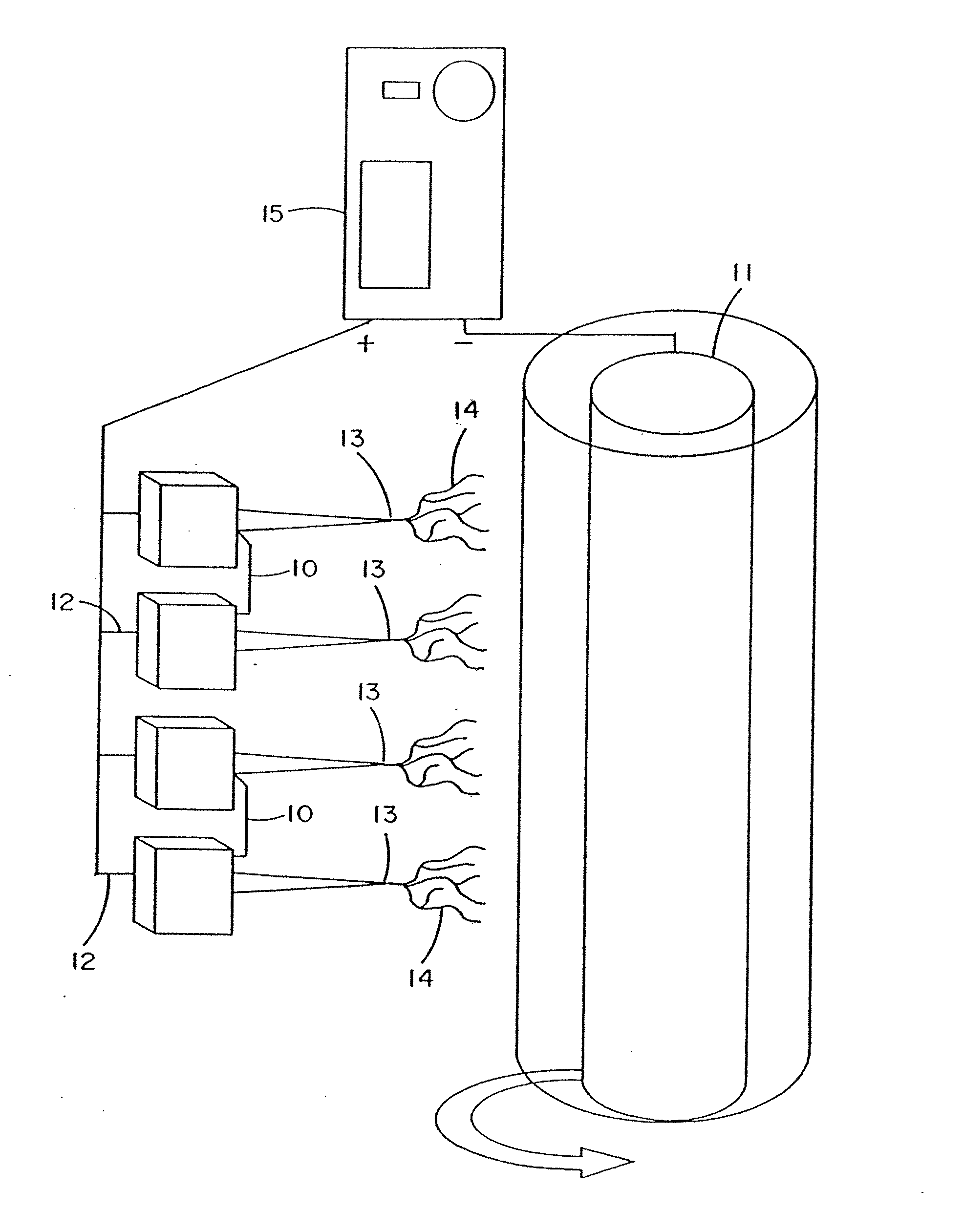
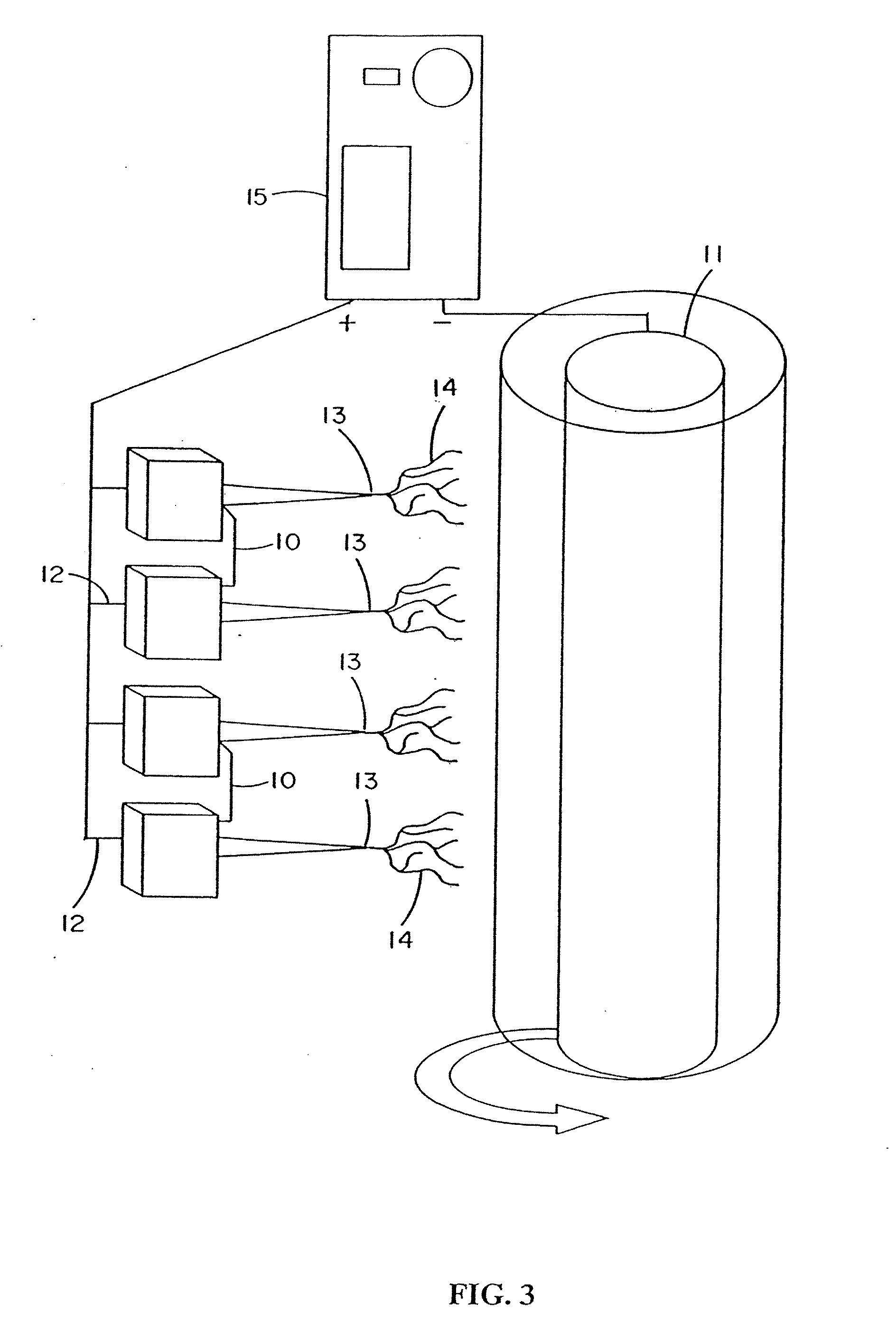
[0011] The present method includes pre-selecting a mold adapted to make the predetermined shape and filling the mold with electroprocessed material or electrodepositing materials on the outer surface of the mold. Further shaping can be accomplished by manual processing of the formed matrices. For example, multiple formed matrices can be sutured, sealed, stapled, or otherwise attached to one another to form a desired shape. The electroprocessed matrix can be milled into a powder or milled and prepared as a hydrated gel composed of banded fibrils. Alternatively, the physical flexibility of many matrices allow them to be manually shaped to a desired structure. The electroprocessed collagen can be processed further, for example by crosslinking or shaping, or placement in a bioreactor for cell culturing. In this way, cells can be grown in an electroprocessed matrix.

Problems solved by technology

Many such polymers, however, suffer the drawbacks associated with their chemical and structural dissimilarities with natural materials.
Fibrotic encapsulation, lack of cellular infiltration, and rejection are problems experienced by such implants.
Many such polymers, however, suffer the drawback of producing major degradation by-products that, in intimate contact with to individual cells, can produce an inflammatory response and decrease the pH in the cellular microenvironment.
Another complication is that bioabsorbable structural materials are degraded over time, resulting in structural failure of the implant.
Fibrotic encapsulation and lack of cellular infiltration also remain problems.
A problem with these constructs is that they either lack structural strength (as with collagen gels) or lose strength after implantation.
This process causes structurally sound implants to lose integrity after implantation and ultimately to fail.

Method used


Image

  • Electroprocessed Collagen and Tissue Engineering
  • Electroprocessed Collagen and Tissue Engineering
  • Electroprocessed Collagen and Tissue Engineering

Examples


example 1

Fibroblast Growth Factor (FGF) Release from an Implant Comprised of Type I Collagen, PGA and PLA

[0272] Fibroblast growth factor (FGF, obtained from Chemicon, Temecula, Calif.) was dissolved in a solution of matrix material comprised of type I collagen (80%), PGA (10%) and PLA (10%). The percentages refer to the weight of the materials with respect to one another. These materials were dissolved in HFIP at a final concentration of 0.08 gm per ml. Sufficient FGF was added to 1 ml of solution to provide an FGF concentration of 50 ng / ml of the collagen / PGA / PLA electrospinning solution. The material was electrospun into the shape of a cylinder onto the outer surface of a grounded and spinning 16 gauge needle about 25-35 mm in length. After completion of electrospinning, the material was removed from the needle and the electrospun cylinder was sutured shut looping a suture around the outside of the construct and pulling tight to seal the ends. A similar result may be obtained by using a ...

example 2

Vascular Endothelial Growth Factor (VEGF) Release from an Implant Material Comprised of Type I Collagen, PGA and PLA

[0273] Vascular endothelial growth factor (VEGF, obtained from Chemicon, Temecula, Calif.) was dissolved in a solution of matrix material comprised of type I collagen (80%), PGA (10%) and PLA (10%) as described in example 1. These materials were dissolved in HFIP at a final concentration of 0.08 gm per ml. Sufficient VEGF was added to 1 ml of solution to provide a VEGF concentration of 50 ng / ml of the collagen / PGA / PLA electrospinning solution. The material was electrospun to form a cylindrical construct and implanted into the rat vastus lateralis muscle using the same procedures set forth in Example 1. VEGF increased the density of functional capillaries that were present throughout the construct. This was evidenced by the presence of capillaries containing red blood cells (RBCs).

example 3

Release of VEGF from Constructs of Electroprocessed Collagen, PGA, and PLA

[0274] Constructs of electroprocessed collagen and PGA:PLA copolymer, with VEGF spun into the matrix were prepared using 80% collagen and 20% PGA:PLA. The collagen and PGA:PLA were dissolved in HFIP at a final combined concentration of 0.08 gm per ml. Solutions were prepared in which different amounts of VEGF were added to 1 ml of the solution of collagen and PGA:PLA copolymer. Separate solutions for electrospinning were prepared containing 0 ng, 25 ng, 50 ng, and 100 ng each of VEGF in 1 ml of electrospinning solution. Constructs were prepared for each solution by electrospinning 1 ml of material onto a cylindrical construct (2 mm in diameter). The constructs were removed from the target needle and cut in half. One half of each electrospun sample was then exposed to glutaraldehyde vapor fixation to cross link the fibers of collagen. Cross-linking was accomplished by exposing the constructs to glutaraldehyde...


PUM

PropertyMeasurementUnit
Thicknessaaaaaaaaaa
Diameteraaaaaaaaaa
Diameteraaaaaaaaaa

Abstract

The invention is directed to formation and use of electroprocessed collagen, including use as an extracellular matrix and, together with cells, its use in forming engineered tissue. The engineered tissue can include the synthetic manufacture of specific organs or tissues which may be implanted into a recipient. The electroprocessed collagen may also be combined with other molecules in order to deliver substances to the site of application or implantation of the electroprocessed collagen. The collagen or collagen / cell suspension is electrodeposited onto a substrate to form tissues and organs.

Description

PRIOR RELATED APPLICATIONS [0001] This application is a continuation-in-part of U.S. Non-Provisional patent application Ser. No. 09 / 991,373 filed Nov. 16, 2001, which is a continuation-in-part of U.S. Non-Provisional patent application Ser. No. 09 / 714,255, filed Nov. 17, 2000, which is a continuation-in-part of U.S. Non-Provisional patent application Ser. No. 09 / 512,081, filed Feb. 24, 2000, which is a continuation-in-part of U.S. Non-Provisional patent application Ser. No. 09 / 386,273, filed Aug. 31, 1999. U.S. Non-Provisional patent application Ser. No. 09 / 512,081 also claims priority, in part, from U.S. Provisional Application Ser. No. 60 / 121,628, filed on Feb. 25, 1999. This application further claims priority from U.S. Provisional Application Ser. No. 60 / 384,035, filed May 28, 2002; U.S. Provisional Application Ser. No. 60 / 386,612, filed Jun. 6, 2002; U.S. Provisional Application Ser. No. 60 / 396,399, filed Jul. 15, 2002; and U.S. Provisional Application Ser. No. 60 / 402,189, file...

Claims


Application Information

Patent Timeline
IPC IPC(8): A61K9/14A61K35/12A61P41/00A61F2/08A61L15/32A61L27/18A61L27/24A61L27/26A61L27/34A61L27/38A61L27/50A61L31/04B29C41/00B29C67/00C07K14/78C12N5/00D01D5/00D01F4/00
CPCA61L31/041A61K2035/126A61F2/08A61L2430/30C12N2533/54A61K38/00Y10T428/298D01D5/0038C12N2533/40D01F1/10A61L27/507C07K14/78A61L27/3839A61L27/24A61L27/26A61L15/32C12N5/0012A61L27/34A61L27/3895B29C67/0007A61L27/3804B29C41/006D01F4/00A61L27/18C12N5/0068C08L67/04C08L89/00C08L89/06Y10T442/60Y10T442/2525Y10T442/614A61P41/00
Inventor SIMPSON, DAVID G.BOWLIN, GARY L.WNEK, GARY E.STEVENS, PETER J.CARR, MARCUS E.MATTHEWS, JAMIL A.RAJENDRAN, SARAVANAMOORTHY
Owner VIRGINIA COMMONWEALTH UNIV INTPROP FOUND INC
Why Eureka
Eureka Blog
Learn More