Battery With Porous Material and Fabrication Method Thereof

Inactive Publication Date: 2008-02-14
LEE KI BANG
View PDF6 Cites 78 Cited by
  • Summary
  • Abstract
  • Description
  • Claims
  • Application Information

AI Technical Summary

Benefits of technology

[0010] It is an objective of the present invention to provide liquid-activated battery to supply electricity that is required by disposable healthcare test kits, bioMEMS (bio Micro Electro Mechanical Systems) and

Problems solved by technology

However, one of the major problems face by current MEMS or bioMEMS, DNA chips, lab-on-a-chip, healthcare test kit, and biosystem technologies is that of the energy source.
Although s

Method used


Image

  • Battery With Porous Material and Fabrication Method Thereof
  • Battery With Porous Material and Fabrication Method Thereof
  • Battery With Porous Material and Fabrication Method Thereof

Examples


Example

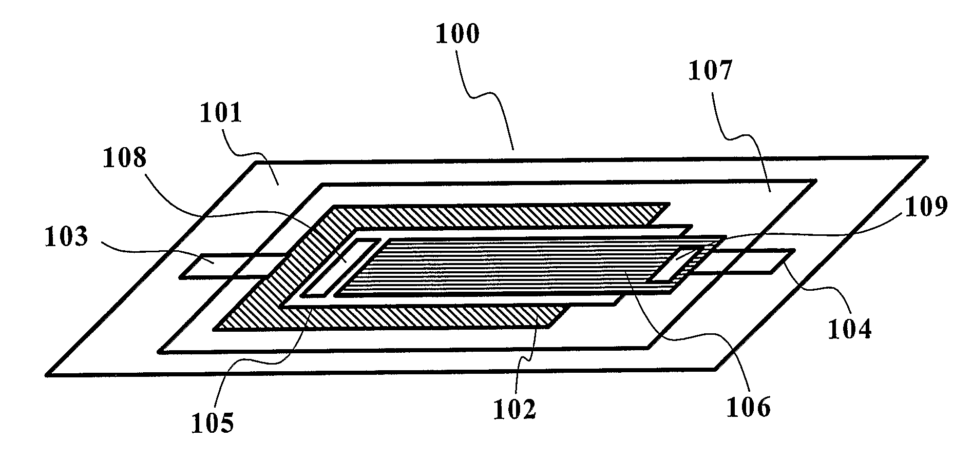
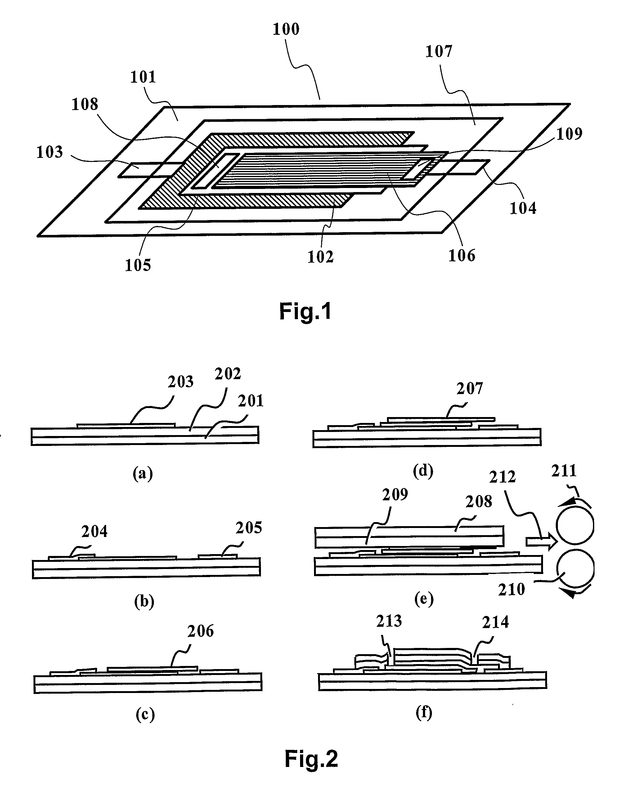
[0082]FIG. 1 show one of the preferred embodiments of the present battery, activated by liquid(water)-activated battery. The battery 100 consists of a sandwich including copper layer 102 for collecting electrons, copper chloride(CuCl)-doped paper 105 and magnesium layer 106 as a anode between lower and upper transparent plastic film 101 and 107. The numbers 103 and 104 are the electrodes for electrical connections of the copper layer 102 and the magnesium layer 106, respectively. The numbers 108 and 109 are the introduction hole (slit) for liquid such as water and biofluid and the air exhalation hole (slit) to be used for air removal from the paper. The copper layer 102 is used for a current collector that collects electron via a load (not shown in FIG. 1) and can be replaced with any other conductive materials. The paper 105 for CuCl is substituted with any other porous materials that have holes or channel for liquid flow. For example, we can use the following in any combination: p...


PUM

PropertyMeasurementUnit
Electrical conductoraaaaaaaaaa
Hydrophilicityaaaaaaaaaa
Surface tensionaaaaaaaaaa

Abstract

The present invention relates to batteries that can be activated by liquid. The battery with porous material is suitable for disposable healthcare test kits, bioMEMS (bio Micro Electro Mechanical Systems) and biosystems such as DNA chips, lab-on-a-chip or micro fluidics and can be easily integrated with disposable devices/systems.

Description

FIELD OF THE INVENTION [0001] The present invention relates to batteries that can be activated by liquid. The battery with porous material is suitable for disposable healthcare test kits, bioMEMS (bio Micro Electro Mechanical Systems) and biosystems such as DNA chips, lab-on-a-chip or micro fluidics and can be easily integrated with disposable devices / systems. BACKGROUND OF THE INVENTION [0002] The advances in the areas of MEMS (Micro Electro Mechanical Systems) and micromachining over the past decades have made possible the fabrication of micro- and nano-level systems such as the lab-on-a-chip, DNA chip, microfluidic devices, optical Microsystems and micro-transceiver. Using batch process such as bulk and surface micromachining technology, these MEMS or bioMEMS devices can be easily fabricated with microactuator, microsensor and circuits on a substrate. Today, the applications of these nano-scale devices have diversified into a myriad of purposes, most notably in the area of the se...

Claims


Application Information

Patent Timeline
IPC IPC(8): H01M14/00H01M2/00H01M2/12H01M50/121
CPCH01M2/0267H01M2/0275H01M2/1626H01M4/46Y10T29/49108H01M6/30H01M6/32H01M6/40Y10T156/10H01M4/582H01M50/4295H01M50/44H01M50/121H01M6/46H01M14/00
Inventor LEE, KI BANG
Owner LEE KI BANG
Why Eureka
Try Eureka