Flooded evaporator

Inactive Publication Date: 2008-02-21
MAYEKAWA MFG CO LTD
View PDF11 Cites 17 Cited by
  • Summary
  • Abstract
  • Description
  • Claims
  • Application Information

AI Technical Summary

Benefits of technology

[0030] According to the flooded evaporator of the invention, the heat exchanger having a number of cooling tubes in which the medium to be cooled flows is immersed in refrigerant liquid in the container to form the heat exchanging section, good heat transfer performance between the medium to be cooled and refrigerant filled in the heat exchanging section specific to a flooded evaporator can be obtained, and mist separation is performed in three steps. The first step is that refrigerant vapor generated in the heat exchanging section and containing refrigerant mist is introduced to the inner tube to flow up in the inner tube, this fluid impinges against the loose cover provided at the top of the inner tube with a clearance retained between the loose cover and the top end of the inner tube to be deflected there to flow downward, the loose cover being formed such that area A of the clearance between the inside periphery of the downwardly extending parts of the loose cover and the outer periphery of the inner tube is smaller than area B of the clearance between the outer periphery of the downwardly extending parts of the loose cover and the inside periphery of the tubular housing (A<B) so that the refrigerant mist contained in the refrigerant vapor is prevented from flowing upward directly together with the refrigerant vapor after the refrigerant vapor containing refrigerant mist flows out passing through the area B and a part of the mist is separated from the refrigerant vapor and falls down due to gravitational attraction aided by downward velocity thereof to return to the heat exchanging section. The second step is that refrigerant mist remaining in the refrigerant vapor is separated in the course of flowing upward in the space above the loose cover due to gravitational attraction. The third step is that the rest of refrigerant mist is removed in the demister. Therefore, refrigerant mist can be exactly separated from refrigerant vapor, as a result liquid flow-back to a device such as a compressor located downstream of the evaporator can be prevented.
[0031] As the flooded evaporator of the invention is composed of a heat exchanging section and a vapor-liquid separating section provided integral with the heat exchanging section to rise upward, the evaporator does not become large sized, space saving is attained, and can be composed to be hermetically-closed easily by composing as welded construction, it can be applied to an ammonia refrigeration system.
[0032] By composing the flooded evaporator preferably such that the heat exchanger is preferably covered with a cover plate such that an upper part of the cover plate where the inner t

Problems solved by technology

When boiling point of refrigerant liquid rises, temperature difference between the temperature of the medium to be cooled and that of refrigerant liquid

Method used


Image

  • Flooded evaporator
  • Flooded evaporator
  • Flooded evaporator

Examples


Example

The First Embodiment

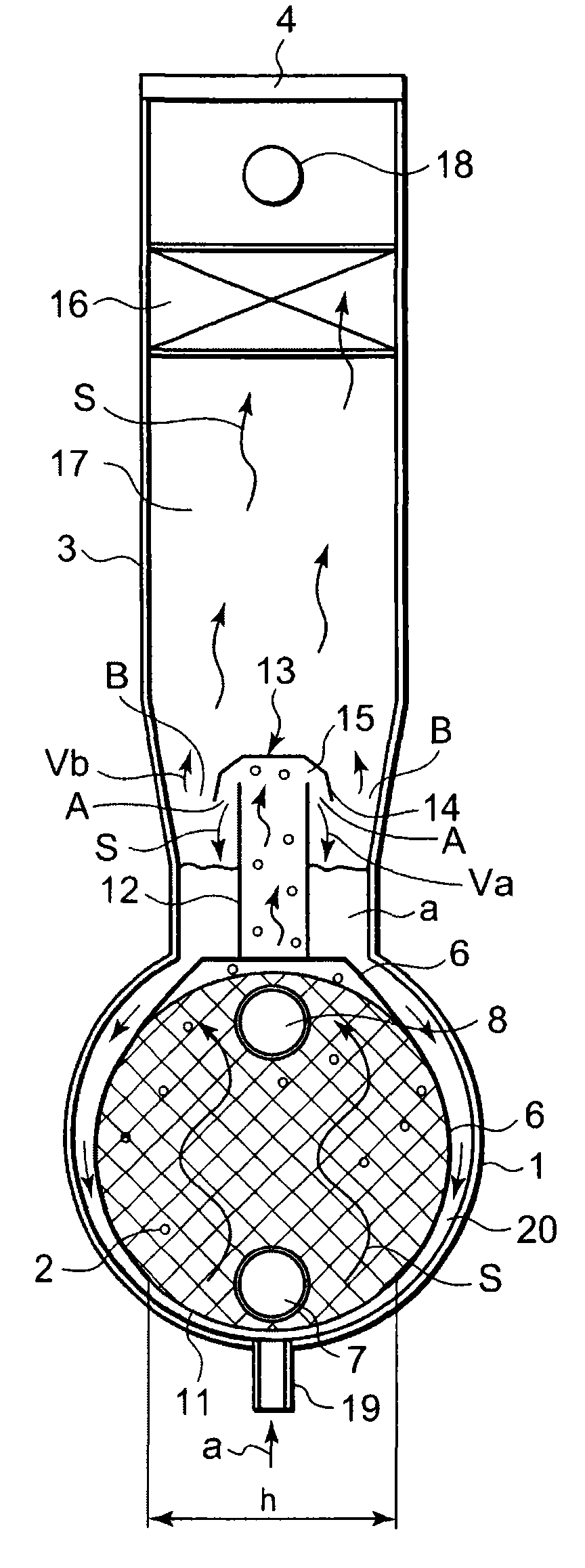
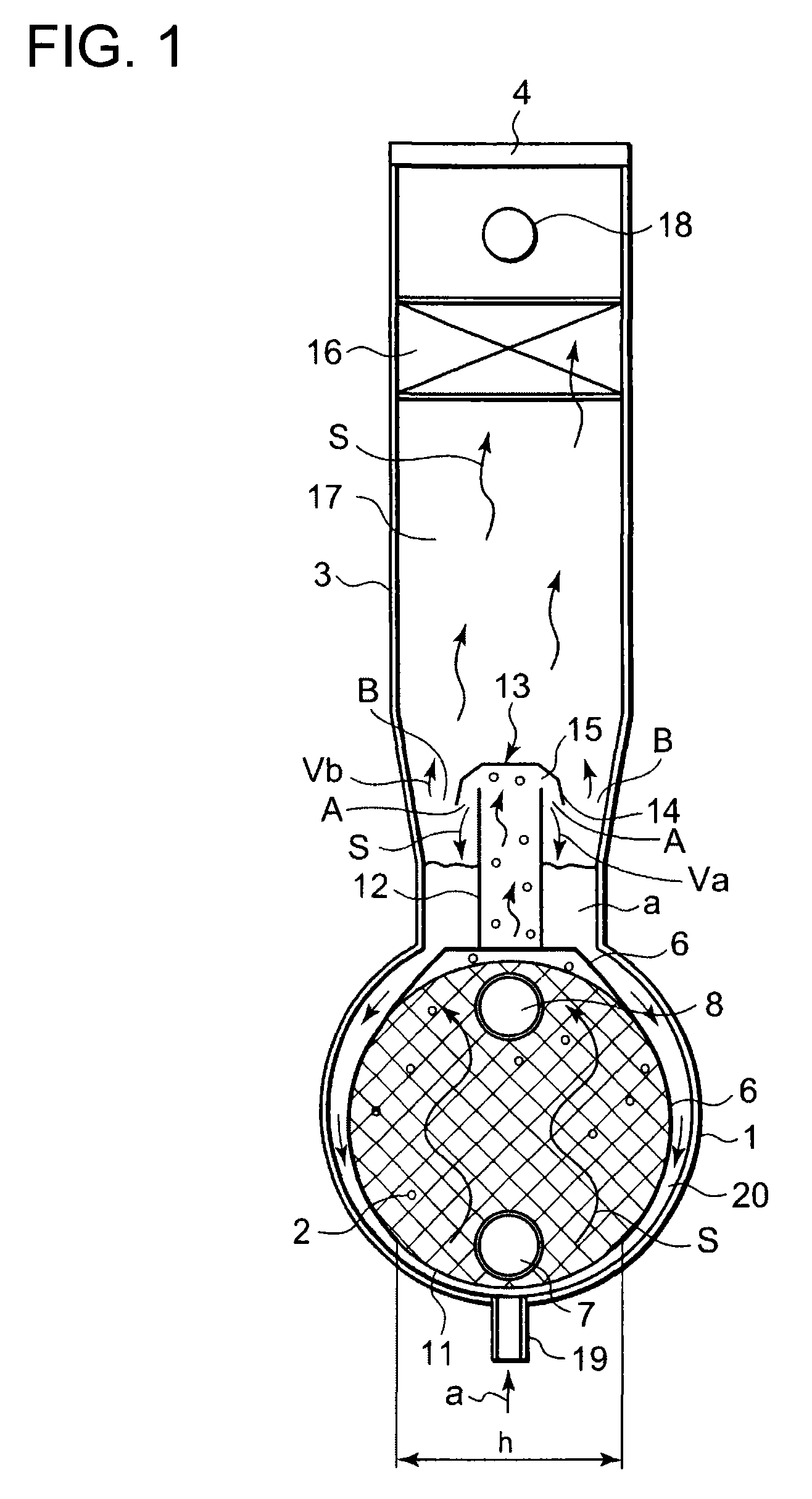
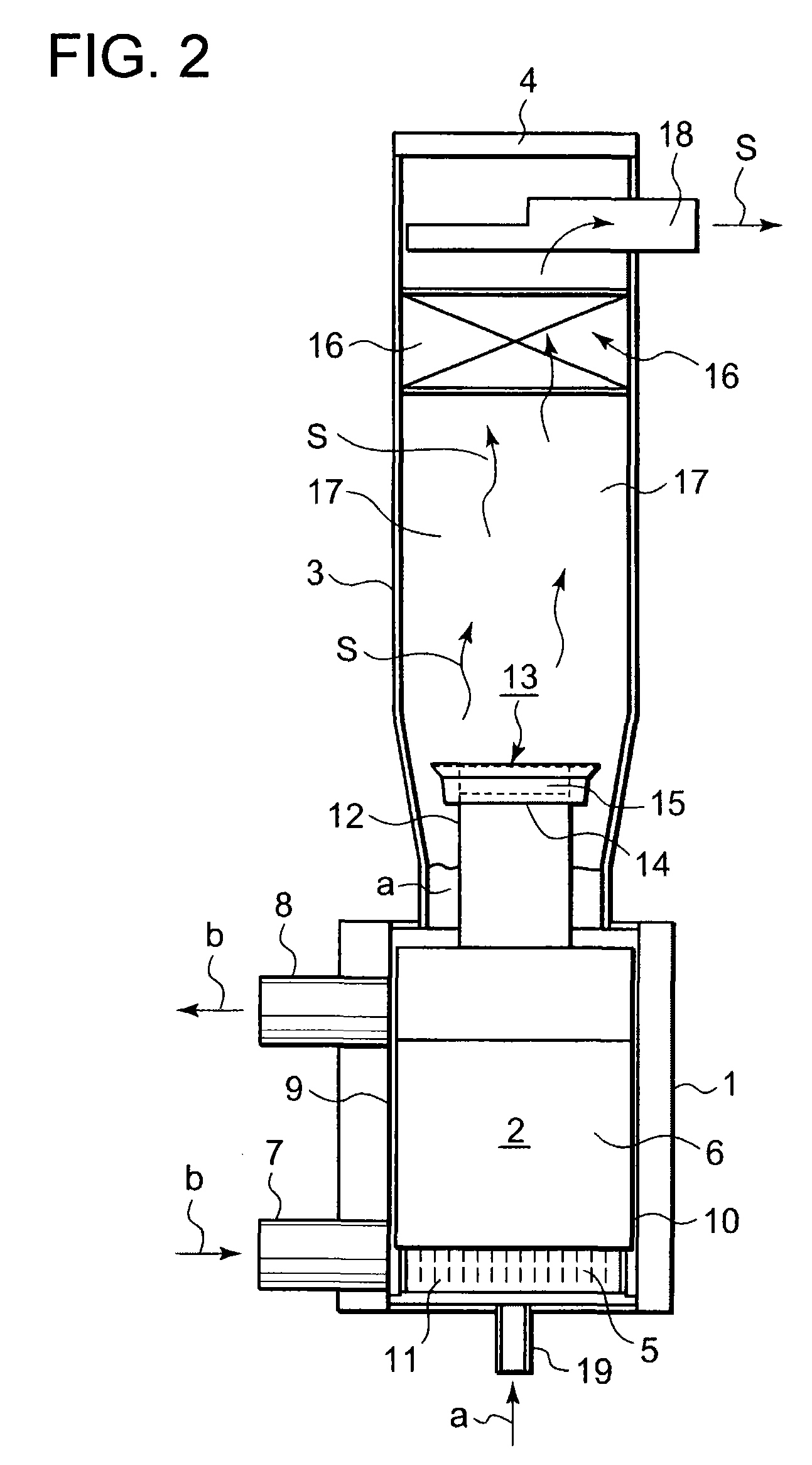
[0065] Referring to FIGS. 1-3, reference numeral 1 is a horizontal cylindrical container in which a heat exchanger 2 is accommodated. Reference numeral 3 is a tubular housing extending upward from the cylindrical container 1 which composes a refrigerant mist separating section. The tubular housing 3 is closed at the top thereof by a cover 4.

[0066] The heat transfer plates 5 are arranged parallel to each other at certain spacing and the upper part of the heat exchanger 2 including the upper part of the heat transfer plates 5 is covered with a cover plate 6. Reference numeral 7 is an inlet pipe for introducing a medium to be cooled ‘b’ and reference numeral 8 is an outlet pipe through which the medium cooled in the heat exchanger 2 flows out from the heat exchanger 2. The inlet pipe 7 and outlet pipe 8 are connected with heat exchanging tubes (not shown in the drawings, intersections of crosshatched lines indicating centers of the heat exchanging tubes) arranged ...

Example

The Second Embodiment

[0080] Next, a second embodiment of the invention will be explained with reference to FIGS. 5-7. The second embodiment is an example of a case the flooded evaporator of the invention is applied to an ammonia refrigerating machine. In FIGS. 5-7, constituents the same as those of FIGS. 1-3 are indicated by the same reference numerals and symbols. Reference numerals 7 and 8 in FIGS. 5-7 are inlet pipes and outlet pipes for introducing and letting out the medium to be cooled and cooled medium into and from the heat exchanger 2 respectively. Unlike the first embodiment, in the second embodiment the inlet pipes 7 and outlet pipes 8 are provided at both ends of the horizontal cylindrical container 1 respectively. The outlet pipe 18 is connected to the upper part of each of two tubular housings 3 so that refrigerant vapor from each of the tubular housings 3 flows together therethrough. Reference numeral 21 is a support member for supporting the supply pipe 19 for intro...


PUM


Abstract

A flooded evaporator is provided which can remove floating mist more exactly resulting in that the refrigerant mist is prevented from being sucked into the compressor, and with which heat transfer between the medium to be cooled and refrigerant liquid is improved. The evaporator is composed such that; a tubular housing (3) is provided to erect from a horizontal cylindrical container (1) which forms a heat exchanging section with a heat exchanger (2) accommodated therein, an inner tube (12) for upwardly guiding refrigerant vapor generated in the heat exchanging section is provided, the inner tube (2) is covered by a loose cover (13) so that refrigerant vapor containing refrigerant mist flowed up in the inner tube (12) impinges against the loose cover (13) to be deflected downward to flow out from the inner tube (12), a space (17) is secured in the tubular housing (3) to allow refrigerant mist to fall down utilizing gravitational attraction, a demister (16) is provided in the tubular housing (3) above the space (17), the clearance area between the inner tube (12) and loose cover (13) is smaller than the clearance area between the outer periphery of the loose cover (13) and inner periphery of the tubular housing (3), and circulation paths (20) of refrigerant liquid are formed in the container (1).

Description

TECHNICAL FIELD [0001] The present invention relates to a flooded evaporator further increased in heat transfer performance of flooded evaporators commonly adopted in refrigerating machines, etc. for their superior heat transfer performance and improved in function of separating refrigerant mist in refrigerant vapor volatilized an the evaporator. BACKGROUND ART [0002] A flooded evaporator is an evaporator in which tubes for allowing a medium to be cooled (water for refrigerated air conditioning, for example) to flow are arranged in refrigerant liquid flooded therein to allow heat exchange between the refrigerant liquid and the medium to be cooled so that the medium is cooled by giving heat to the refrigerant liquid to allow it to evaporate. The heat exchange is performed effectively because heat transfer from liquid through the tube wall is superior. [0003] Refrigerant vapor to be introduced into a compressor located downstream of the evaporator must be got rid of refrigerant mist i...

Claims


Application Information

Patent Timeline
IPC IPC(8): F25B39/02
CPCF25B39/02F25B2339/0242F28D21/0017F28D9/0006F25B2500/28
Inventor SAKASHITA, SHIGERUTAKEDA, MASATONELSON, MUGABIFURUYA, KOUICHIKOMEDA, MASAOONODERA, FUMIAKIHAYASHI, RYUJI
Owner MAYEKAWA MFG CO LTD
Why Eureka
Try Eureka