Polarization independent optical isolator and optical transmitting/receiving apparatus

Active Publication Date: 2008-02-21
FUJITSU LTD
View PDF1 Cites 16 Cited by
  • Summary
  • Abstract
  • Description
  • Claims
  • Application Information

AI Technical Summary

Benefits of technology

[0036]According to the present invention, there can be provided the polarization independent

Problems solved by technology

However, the method of Prior Art 1 causes a problem in that the optical device is upsized as much as the increased thicknesses of the first birefringent plate 1 and the second birefringent plate 4.
T

Method used


Image

  • Polarization independent optical isolator and optical transmitting/receiving apparatus
  • Polarization independent optical isolator and optical transmitting/receiving apparatus
  • Polarization independent optical isolator and optical transmitting/receiving apparatus

Examples


Example

First Embodiment

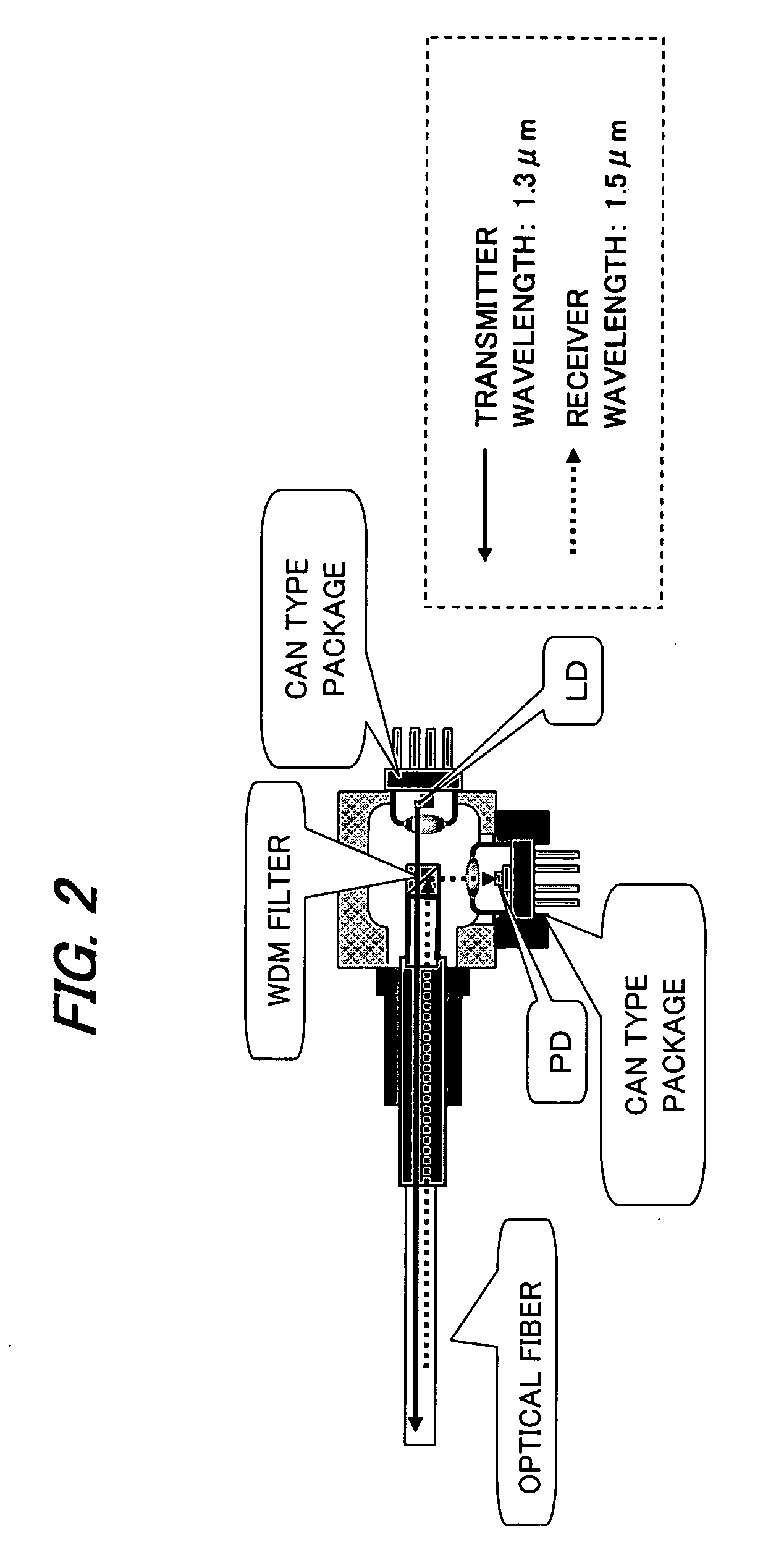
[0049]FIG. 8 is a diagram showing a structural example of an optical device (optical transmitting / receiving apparatus) according to a first embodiment of the present invention. Referring to FIG. 8, the optical transmitting / receiving apparatus includes an optical fiber F as an optical transmission path, a CAN type package (hereinafter referred to as “LD package”) 10 (corresponding to a second CAN type package) which receives an LD as a light emitting element (light source), a CAN type package (hereinafter referred to as “PD package”) 20 (corresponding to a second CAN type package) which receives a PD as a light receiving element, and a polarization independent optical isolator 30 (hereinafter referred to as “optical isolator 30”).

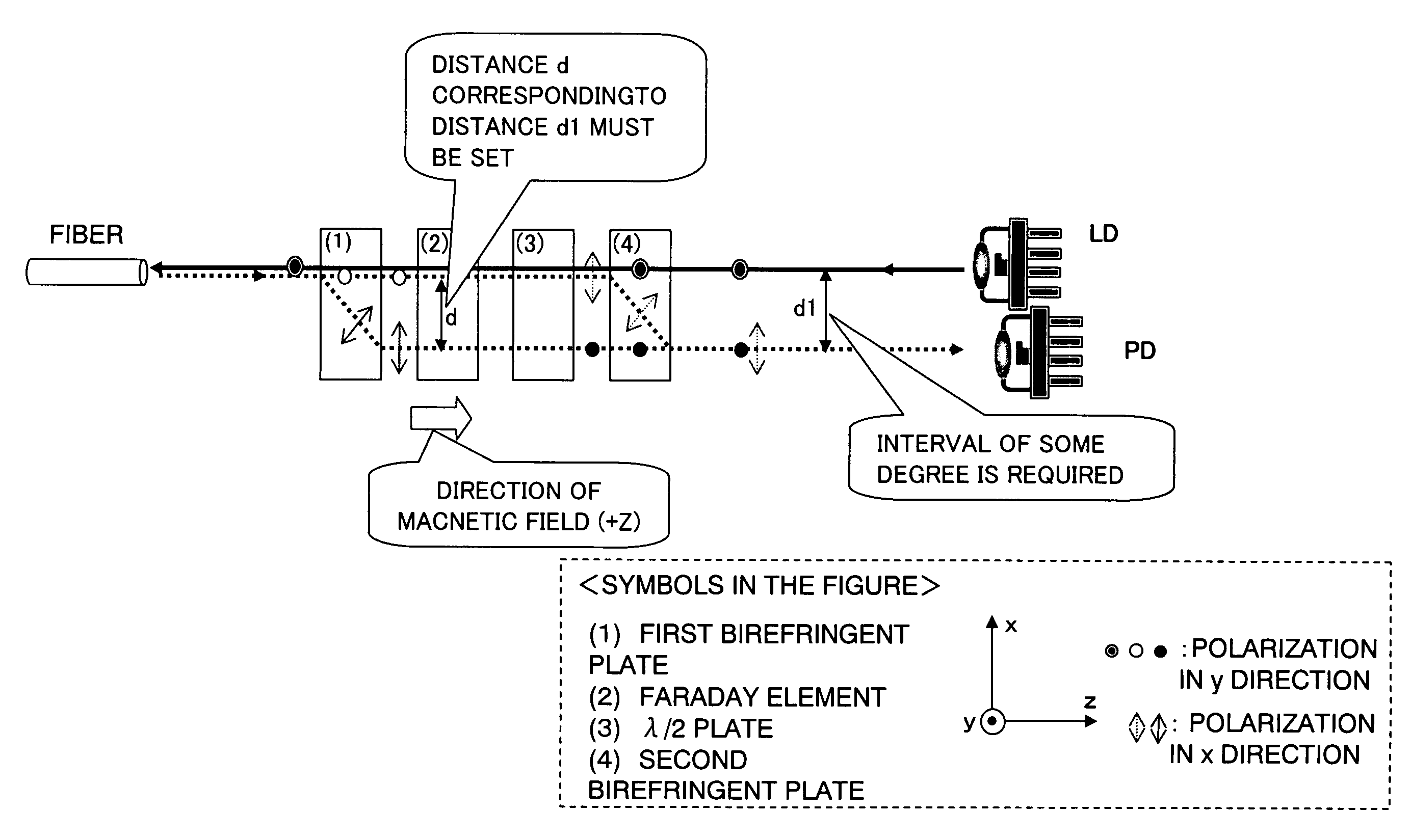
[0050]The optical isolator 30 includes a first birefringent plate 1 (hereinafter referred as “birefringent plate 1”), a Faraday element (Faraday rotator) 2, a λ / 2 plate (½ wavelength plate) 3, a polarization beam splitter 6 (corresponding to ...

Example

Second Embodiment

[0062]FIG. 9 is a diagram showing a structural example of an optical transmitting / receiving apparatus according to a second embodiment of the present invention. In the optical transmitting / receiving apparatus shown in FIG. 8, the LD module 10 is disposed at the upper side of the optical isolator 30, whereas in the optical transmitting / receiving apparatus shown in FIG. 9, the LD module 10 is disposed at the lower side of the optical isolator 30. With this structure, the input direction of the transmitter light with respect to the polarization beam splitter 6 is different from that in the first embodiment. Except for the above-mentioned matters, the structure and operation of the optical transmitting / receiving apparatus (optical transmitter and receiver) according to the second embodiment are identical with those in the first embodiment, and therefore their description will be omitted.

Example

Third Embodiment

[0063]FIG. 10 is a diagram showing a structural example of an optical transmitting / receiving apparatus according to a third embodiment of the present invention. FIG. 10 shows an example in which the LD package 10, the PD package 20, the optical isolator 30, and the optical fiber F which constitute the optical transmitting / receiving apparatus described in the first embodiment are structured integrally.

[0064]Referring to FIG. 10, the optical transmitting / receiving apparatus has a hollow boxy housing 40. The housing 40 includes opening portions 41 and 42 into which a CAN portion 11 of the LD package 10 and a CAN portion 21 of the PD package 20 are to be inserted, and the respective CAN portions 11 and 21 are inserted into the opening portions 41 and 42, respectively, and flange portions 12 and 22 of the respective packages 10 and 20 are abutted against the outer surface of the housing 40. The respective packages 10 and 20 are fixed to the housing 40 at the abutment port...


PUM


Abstract

A polarization independent optical isolator includes: a first birefringent plate that divides the receiver light from the optical transmission path into normal light and abnormal light to output the normal light and the abnormal light; a second birefringent plate that combines the normal light and the abnormal light to output the combined light to the light receiving element; an optical rotation unit that is disposed between the first birefringent plate and the second birefringent plate, rotates the polarization direction of the normal light and the abnormal light which are outputted from the first birefringent plate by substantially 90° and outputs the rotated light, and outputs the reflected light of the receiver light in a state where the polarization direction of the reflected light is not rotated; and a polarizing element that is disposed between the optical rotation unit and the second birefringent plate, allows one of the normal light and the abnormal light which are inputted from the optical rotation unit to pass therethrough and to be inputted to the second birefringent plate, and outputs the transmitter light inputted from the light emitting element to the optical rotation unit.

Description

BACKGROUND OF THE INVENTION[0001]1. Field of the Invention[0002]The present invention relates to a polarization independent optical isolator and an optical transmitting / receiving apparatus, and more particularly, to an LD / PD (laser diode / photo diode) integrated optical device in an optical module that is used in a communication system which transmits and receives a signal through a single line bi-directionally.[0003]2. Description of the Related Art[0004]In recent years, a PON (passive optical network) system has been widely employed in an optical fiber access network. The PON system is a communication network in which an optical signal from an OLT (optical line terminal) serving as a base station side device is split by a star coupler, and then shared by a plurality of subscriber side devices ONU (optical network unit). A down signal from the OLT is used with a wavelength of 1.55 μm band, and an up signal from the ONU is used with a wavelength of 1.3 μm band.[0005]As an optical mod...

Claims


Application Information

Patent Timeline
IPC IPC(8): H01J40/14G02F1/01
CPCG02F1/093
Inventor TANAKA, HIROMASAMORI, KAZUYUKI
Owner FUJITSU LTD
Why Eureka
Try Eureka