Duty cycle correction (DCC) circuit and delayed locked loop (DLL) circuit using the same

Active Publication Date: 2008-02-21
SK HYNIX INC
View PDF10 Cites 27 Cited by
  • Summary
  • Abstract
  • Description
  • Claims
  • Application Information

AI Technical Summary

Benefits of technology

[0011]The present disclosure relates to a Duty Cycle Correction (DCC) circuit for preventing an internal clock signal, in which a variation of internal delay elemen

Problems solved by technology

However, if the above-mentioned synchronous memory synchronizes its data with the external clock signal, and outputs the synchronized result, an unexpected delay of “tAC” (output data Access time from Clk) occurs, and the number of valid data windows is reduced, such that an unexpected faulty operation occurs in the synchronous memory which is o

Method used


Image

  • Duty cycle correction (DCC) circuit and delayed locked loop (DLL) circuit using the same
  • Duty cycle correction (DCC) circuit and delayed locked loop (DLL) circuit using the same
  • Duty cycle correction (DCC) circuit and delayed locked loop (DLL) circuit using the same

Examples


Embodiment Construction

[0026]Specific preferred embodiments of the present disclosure will be described in detail with reference to the annexed drawings. In the drawings, the same or similar elements are denoted by the same reference numerals even though they are depicted in different drawings. In the following description, a detailed description of known functions and configurations incorporated herein will be omitted when it may make the subject matter of the present disclosure rather unclear.

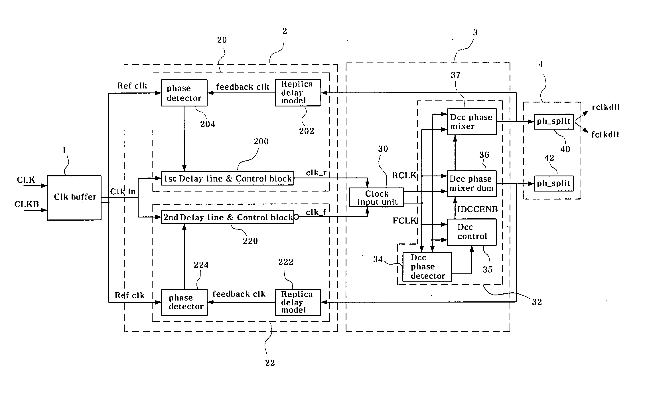
[0027]FIG. 2 shows a DCC circuit according to a preferred embodiment of the present disclosure. FIG. 3 shows a circuit diagram illustrating a clock input unit of a DCC circuit according to a preferred embodiment of the present disclosure. FIG. 4 is a circuit diagram illustrating an example of the multiplexer shown in FIG. 3.

[0028]Referring to FIG. 2, the DLL circuit according to the preferred embodiment of the present disclosure includes a clock buffer 1, a DLL unit 2, a DCC unit 3, and a drive 4.

[0029]The clock bu...


PUM


Abstract

A duty cycle correction (DCC) circuit and a delayed locked loop (DLL) circuit using the same are disclosed. The DCC circuit is operated by an enable signal which is enabled when the DLL is locked. The duty cycle correction (DCC) circuit includes a clock input unit and a duty cycle mixing unit. The clock input unit receives the enable signal and first and second clock input signals having opposite phases, generates an inverting signal of the first clock input signal, and when the enable signal is enabled, generates first and second internal clock signals, based on the first and second clock input signals and the inverting signal. The duty cycle mixing unit mixes a phase of the first internal clock signal with a phase of the second internal clock signal.

Description

BACKGROUND[0001]The present disclosure relates to a Duty Cycle Correction (DCC) circuit and a Delayed Locked Loop (DLL) circuit using the same, and more particularly to a DCC circuit for preventing an internal clock signal, in which a variation of internal delay elements created by an external factor (e.g., a power-supply voltage variation) is insufficiently reflected, from being generated, and a DLL circuit using the DCC circuit.[0002]With the increasing degree of integration of a semiconductor memory, the semiconductor memory has been continuously improved to enhance its operation speed. In order to enhance the operation speed of the semiconductor memory, a synchronous memory device capable of being synchronized with a clock signal received from an external part of a memory chip has been recently introduced to the market.[0003]However, if the above-mentioned synchronous memory synchronizes its data with the external clock signal, and outputs the synchronized result, an unexpected ...

Claims


Application Information

Patent Timeline
IPC IPC(8): H03L7/06
CPCH03L7/07H03L7/095H03L7/0812H03L7/0816G11C8/00
Inventor KIM, SU HYUNYOO, MIN YOUNG
Owner SK HYNIX INC
Why Eureka
Try Eureka