Target Object Detection System

a detection system and target technology, applied in the field of radar systems, can solve problems such as far from practical, and achieve the effect of simplifying the transmission frequency-modulation circuit and narrowing the necessary frequency-modulation bandwidth

Active Publication Date: 2008-02-21
MITSUBISHI ELECTRIC CORP
View PDF21 Cites 31 Cited by
  • Summary
  • Abstract
  • Description
  • Claims
  • Application Information

AI Technical Summary

Benefits of technology

[0016] According to a target object detection system of the present invention, while making use of a conventional two-frequency CW or multi-frequency CW method with its features being kept intact, measurement values can be obtained that satisfy a desired velocity resolution in a measurement time shorter than that by the con

Problems solved by technology

Since a possible frequency bandwidth to be assigned to vehicle-mounted radars, however, is presumed to be on the order of one GHz, at

Method used


Image

  • Target Object Detection System
  • Target Object Detection System
  • Target Object Detection System

Examples


embodiment 1

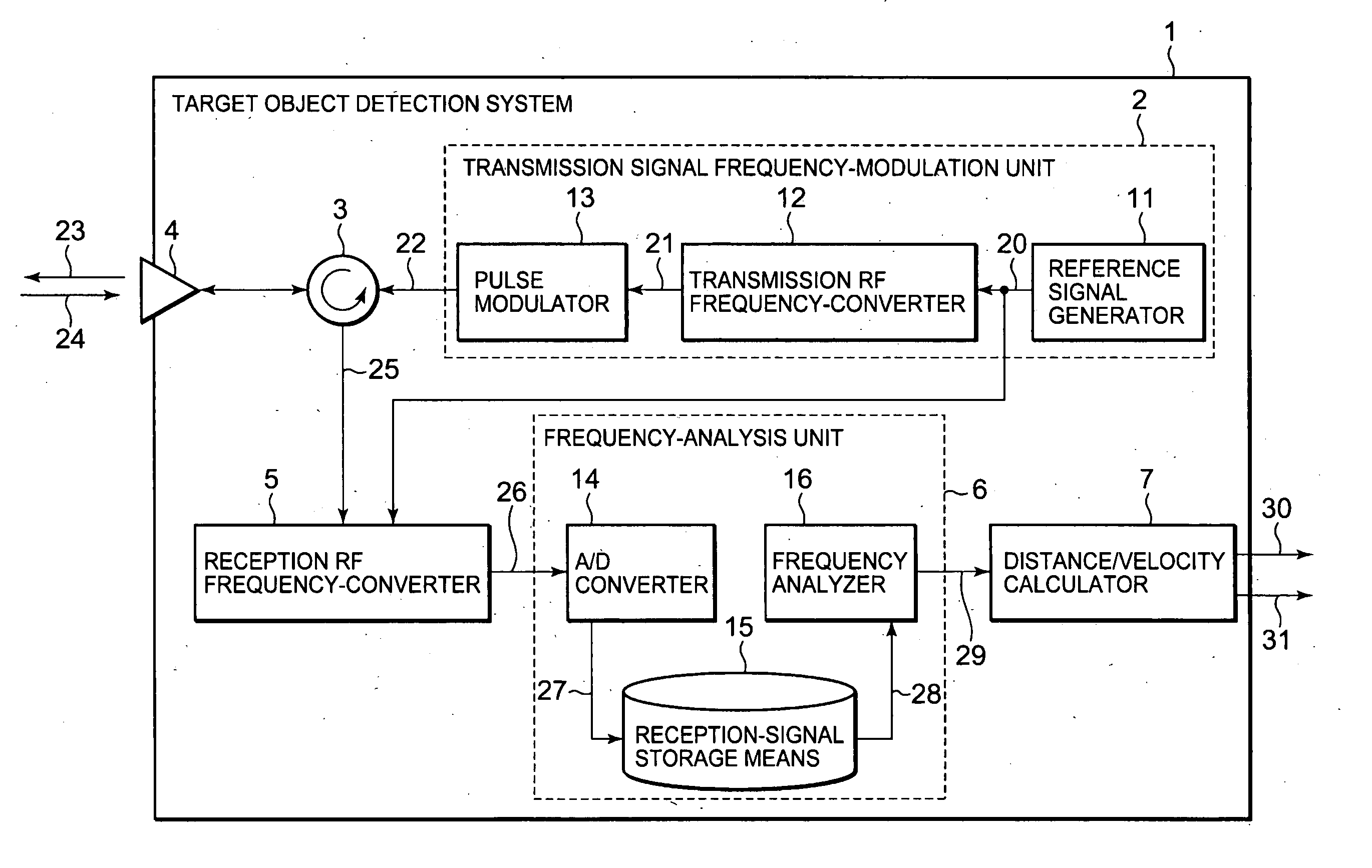
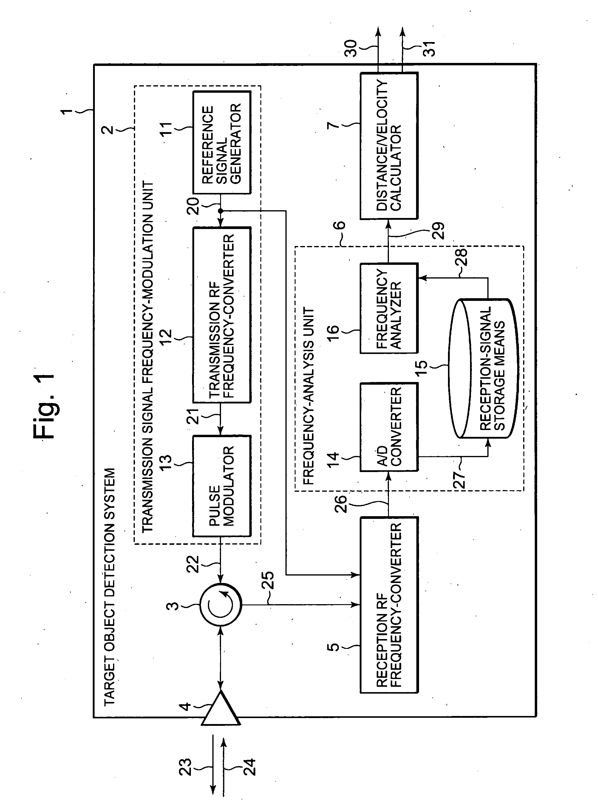
[0035]FIG. 1 is a block diagram illustrating a configuration of a target object detection system according to Embodiment 1 of the present invention. Referring to the figure, the target object detection system 1 is provided with a transmission-signal frequency-modulation unit 2, a circulator 3, a transmit / receive antenna 4, a reception RF frequency-converter 5, a frequency-analysis unit 6, and a distance / velocity calculator 7.

[0036] The transmission-signal frequency-modulation unit 2 has a circuit that generates transmission signals and modulates the frequencies of the generated transmission signals into those according to a predetermined waveform. An example of a detailed configuration of the transmission-signal frequency-modulation unit 2 is further shown in FIG. 1. The transmission-signal frequency-modulation unit 2 according to the configuration example is composed of a reference signal generator 11, a transmission RF frequency-converter 12, and a pulse modulator 13.

[0037] The ...

embodiment 2

[0059] When there exists a plurality of target objects traveling at the same relative speed, a radar system using a conventional two-frequency CW method has a problem in that distances to each target object cannot be correctly discriminated. On the roads where vehicle-mounted radars are mostly used, a situation occurs with great frequency in which a plurality of vehicles travels at nearly the same speed in the same direction. A problem with radar system employing the conventional two-frequency CW method, however, has been that distances to each target object cannot be correctly discriminated in such situation, which has been a hindrance to its practical use.

[0060] In order to solve such problem, a method has been known that discriminates distances to a plurality of target objects traveling at the same speed, by introducing linear modulation into part of frequency modulation periods of transmission waves in a two-frequency CW radar so as to execute processes similar to an FMCW metho...


PUM


Abstract

A time needed until measurement values are obtained in a two-frequency continuous wave radar systems is reduced.
A target object detection system (1) that emits to target objects transmission signals (22), as transmission waves (23), whose frequencies have been modulated successively into a plurality of stepped frequencies, and receives echoes (24) of the transmission waves (23) reflected from the target objects, thereby to calculate relative velocities of the target objects by frequency-analyzing reception signals (25) obtained from the received echoes (24). The target object detection system (1) includes: a frequency modulation means (2) that executes a plurality of times frequency-modulation processes to successively modulate the transmission signals (22) into those of the stepped frequencies, within a minimum measurement time in which a desired velocity resolution is achieved; and a frequency-analysis means (6) that frequency-analyzes throughout the plurality of frequency-modulation processes the reception signals (25) obtained by receiving the echoes (24) of the transmission signals (22) modulated into those of an identical stepped frequency in the plurality of frequency-modulation processes iterated by the frequency-modulation means (2).

Description

TECHNICAL FIELD [0001] The present invention relates to radar systems that detect speeds and the like of target objects by emitting radio waves thereto. BACKGROUND ART [0002] Recently, there have been active studies that attempt to enhance driving safety by mounting on a vehicle such as an automobile a radar system that automatically detects surrounding obstacles and the like to make use of the detection results for vehicle cruise control. The radar system used in the vehicle cruise control needs to detect relative speed information on obstacles and other vehicles with high accuracy. [0003] While such radar system detects speeds, positions, and the like of target objects by frequency-analyzing reception signals obtained by receiving incoming radio waves from the target objects, in order to improve frequency resolution in the frequency analysis of the reception signals, it is necessary to receive the signals for more than a predetermined time period. Taking more time for measurement ...

Claims


Application Information

Patent Timeline
IPC IPC(8): G01S13/58G01S13/931
CPCG01S13/34G01S13/931G01S13/536
Inventor INABA, TAKAYUKI
Owner MITSUBISHI ELECTRIC CORP
Why Eureka
Try Eureka