Color electro-optic displays, and processes for the production thereof

a technology of electrooptic displays and color, applied in the direction of electrographic processes, originals for photomechanical treatment, instruments, etc., can solve the problems of inadequate service life of these displays, unable to meet the needs of use, and gas-based electrophoretic media are susceptible to the same types of problems, so as to enhance the adhesion of ink

Inactive Publication Date: 2008-02-21
E INK CORPORATION
View PDF99 Cites 286 Cited by
  • Summary
  • Abstract
  • Description
  • Claims
  • Application Information

AI Technical Summary

Benefits of technology

[0059] This aspect of the present invention may hereinafter for convenience be called the “protective layer printing” or “PLP” aspect of the invention. Typically, this process will be used to print a full color filter array having two, three or four colors, although more colors can be used if desired. Thus, in a typical PLP process, a plurality of first colored areas and a plurality of second colored areas are printed on the surface of the layer of electro-

Problems solved by technology

Nevertheless, problems with the long-term image quality of these displays have prevented their widespread usage.
For example, particles that make up electrophoretic displays tend to settle, resulting in inadequate service-life for these displays.
Such gas-based electrophoretic media appear to be susceptible to the same types of problems due to particle settling as liquid-based electrophoretic media, when the media are used in an orientation which permits such settling, for example in a sign where the medium is disposed in a vertical plane.
Indeed, particle settling appears to be a more serious problem in gas-based electrophoretic media than in liquid-based ones, since the lower viscosity of gaseous suspending fluids as compared with liquid ones allows more rapid settling of the electrophoretic particles.
However, the methods used for assembling LCD's cannot be used with encapsulated electrophoretic displays.
This LCD assembly process cannot readily be transferred to solid electro-optic displays.
As discussed in the aforementioned U.S. Pat. No. 6,312,304, the manufacture of solid electro-optic displays also presents problems in that the optical components (the electro-optic medium) and the electronic components (in the backplane) have differing performance criteria.
Therefore, a process for manufacturing an optical component may not be ideal for manufacturing an electronic component, and vice versa.
The processing temperature can be in the range from about 300° C. to about 600° C. Subjecting many optical components to such high temperatu

Method used


Image

  • Color electro-optic displays, and processes for the production thereof
  • Color electro-optic displays, and processes for the production thereof
  • Color electro-optic displays, and processes for the production thereof

Examples


example 1

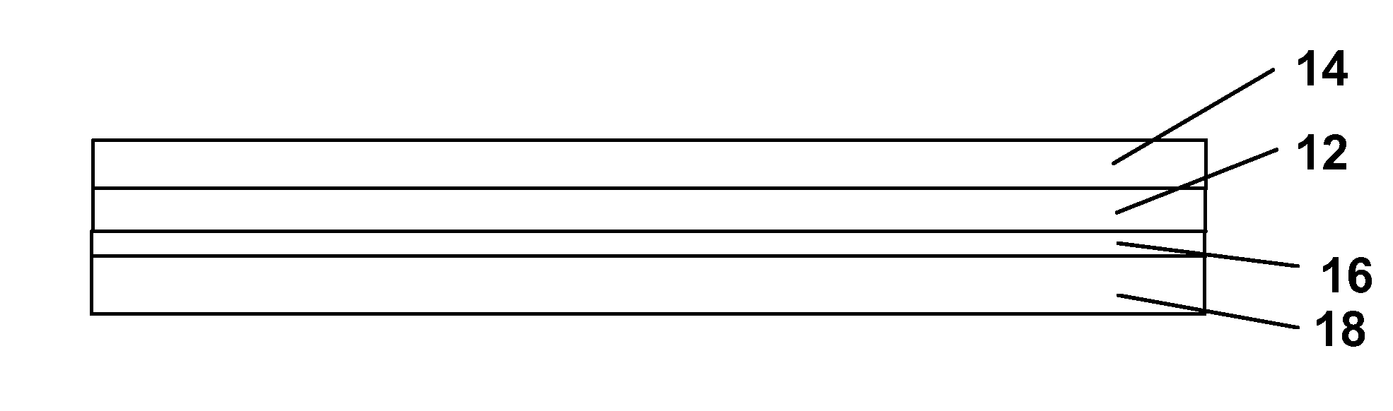
[0104] This Example illustrates an adhesive layer printing process of the present invention using Construction Method C described above.

[0105] An encapsulated electrophoretic medium was prepared comprising gelatin / acacia capsules having an internal phase comprising polymer-coated titania white particles and polymer-coated copper chromite black particles in a hydrocarbon fluid. The capsules were formed into a slurry using an aqueous polyurethane binder substantially as described in Example 4 of the aforementioned U.S. Pat. No. 7,002,728. The resultant capsule slurry was slot coated on to a loose release sheet and dried to form a loose release sheet / capsule layer sub-assembly. Separately, a custom polyurethane adhesive was coated on to a tight release sheet, and then laminated to the loose release sheet / capsules layer sub-assembly, with the adhesive layer contacting the capsule layer. Separately, a polyacrylate adhesive was coated on to a loose release sheet. The loose release sheet ...

example 2

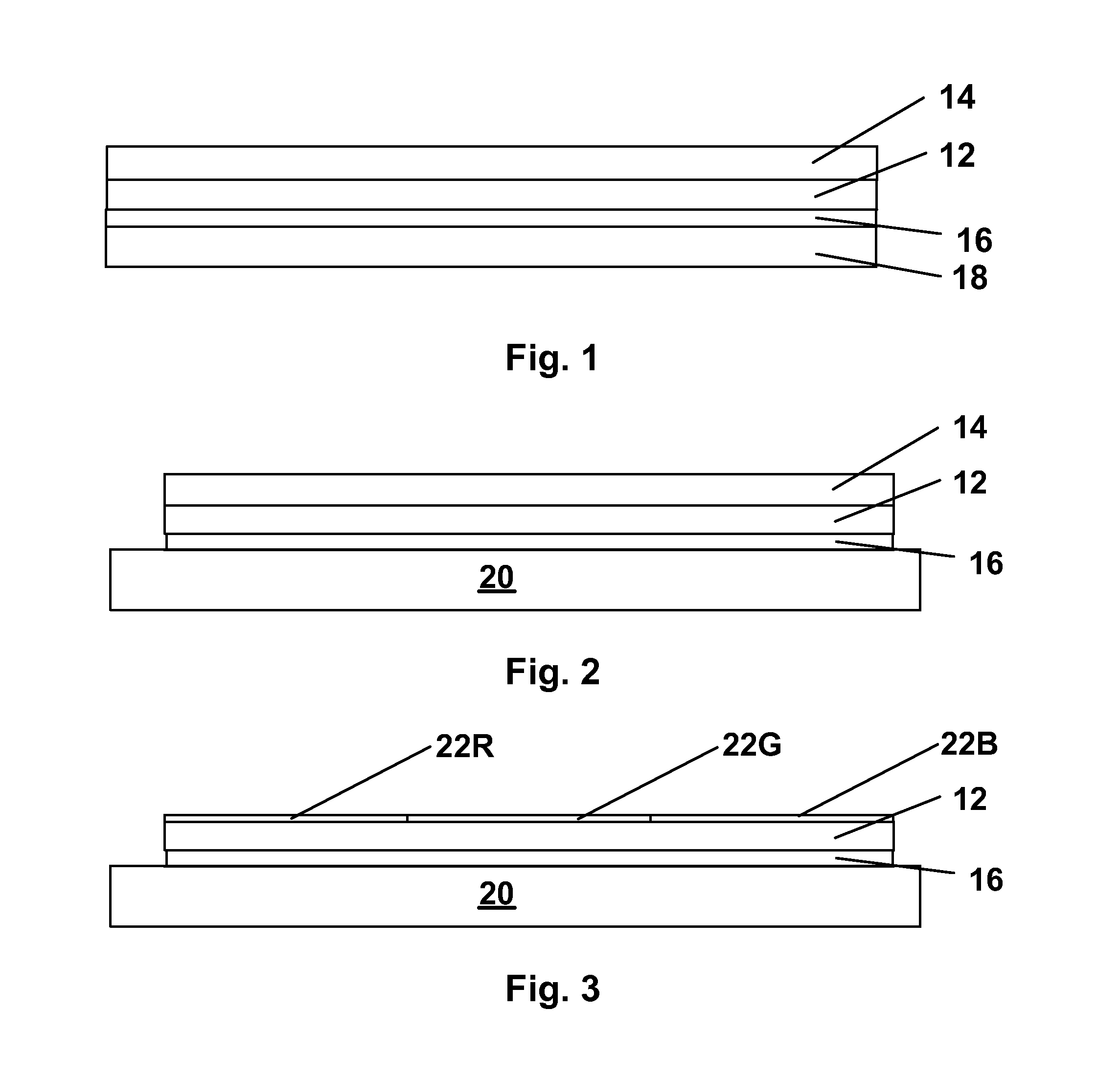
[0110] This Example illustrates a printed protective layer process of the present invention using Construction Method A above.

[0111] An encapsulated electrophoretic display was prepared by coating capsules similar to those described in Example 1 above on the ITO-coated surface of a PET / ITO film and drying, separately coating a custom polyurethane adhesive on to a release sheet, and laminating the adhesive / release sheet sub-assembly to the PET / ITO / capsule layer sub-assembly, with the adhesive contacting the capsule layer to form a front plane laminate. This front plane laminate was cut to size, the release sheet removed and the remaining layers laminated to a thin film transistor active matrix backplane to form a monochrome display. All the preceding steps were carried out substantially as described in the aforementioned U.S. Pat. No. 6,982,178.

[0112] The display thus prepared was ink jet printed using the same printer and inks as in Example 1 above. Printing was effected using the...


PUM

PropertyMeasurementUnit
Electrical conductoraaaaaaaaaa
Electric potential / voltageaaaaaaaaaa

Abstract

A color filter array is provided in an electro-optic display by ink jet printing a plurality of colored areas (22R, 22G, 22B) on one surface of a layer of electro-optic material (12), an adhesive layer or a protective layer. Alternatively, the ink jet printing may be effected on the same layers in various sub-assemblies used to produce electro-optic displays.

Description

REFERENCE TO RELATED APPLICATIONS [0001] This application claims benefit of Application Ser. No. 60 / 825,933, filed Sep. 18, 2006. [0002] This application is also a continuation-in-part of copending application Ser. No. 11 / 550,114, filed Oct. 17, 2006 (Publication No. 2007 / 0109219), which itself claims benefit of Application Ser. No. 60 / 596,743, filed Oct. 18, 2005, and of Application Ser. No. 60 / 596,799, filed Oct. 21, 2005. [0003] This application is also related to: [0004] (a) application Ser. No. 10 / 249,957, filed May 22, 2003 (now U.S. Pat. No. 6,982,178), which claims benefit of Application Ser. No. 60 / 319,300, filed Jun. 10, 2002, and Application Ser. No. 60 / 320,186, filed May 12, 2003; [0005] (b) application Ser. No. 10 / 907,065, filed Mar. 18, 2005 (now U.S. Pat. No. 7,236,292), which is a divisional of the aforementioned application Ser. No. 10 / 249,957; [0006] (c) copending application Ser. No. 11 / 747,546, filed May 11, 2007, which is a continuation of the aforementioned app...

Claims


Application Information

Patent Timeline
IPC IPC(8): G02F1/01G03F1/00G02F1/167G02F1/1677
CPCG02F1/133516G02F1/167Y10T29/49002Y10T428/24802G02F2001/1672G02F1/1681G02F1/1677G02B5/201
Inventor WHITESIDES, THOMAS H.OLESON, ANDREW Y.DANNER, GUY M.PAOLINI, RICHARD J. JR.HONEYMAN, CHARLES HOWIE
Owner E INK CORPORATION
Why Eureka
Try Eureka