
Electromagnetic fuel pump

a fuel pump and electromagnetic technology, applied in the direction of pump components, positive displacement liquid engines, pump parts, etc., can solve the problems of increasing the cost of electromagnetic fuel pumps, achieve excellent fuel delivery efficiency, avoid chip generation, and reduce a number of parts

Inactive Publication Date: 2008-02-21
NIKKI CO LTD
View PDF6 Cites 3 Cited by
  • Summary
  • Abstract
  • Description
  • Claims
  • Application Information

AI Technical Summary

Benefits of technology

[0009]The present invention intends to solve the problem mentioned above, and an object of the present invention is to achieve a cost saving by reducing a number of parts relating to a layout of a check valve and making a cleaning step after assembling unnecessary, in a plunger type electromagnetic fuel pump.
[0011]As mentioned above, since the return spring guide retaining the valve member of the check valve via the return spring is integrally provided with the fixing structure for fixing it so as to form the spring retaining member, any fastening clip constituted by an independent part is not necessary as the fixing member, so that it is possible to avoid generation of a chip caused by an installation of the fastening clip as well as it is possible to reduce a number of the parts, thereby making a cleaning work after assembling unnecessary.
[0012]Further, in the case that the check valves provided with the spring retaining members are provided at two positions on an upstream side and on a downstream side of the pressurizing chamber, a delivery efficiency of the fuel is excellent and the parts reduction can be achieved at two positions.
[0013]Further, in the electromagnetic fuel pump mentioned above, in the case that the fixing structure of the spring retaining member comprises an outer peripheral side extending from the proximal end side of the spring guide in a centrifugal direction with respect to a center axis of the fuel passage, the outer peripheral side of the spring retaining member being fitted in an inner peripheral surface of the mounted position in close contact therewith, the spring retaining member being fixed on the basis of an elastic repulsion force of the fixing structure itself, it is possible to easily form by a comparatively simple structure.
[0014]Further, in the electromagnetic fuel pump mentioned above, in the case that the spring retaining member is made of a synthetic resin having an appropriate elasticity, it is easy to have a suitable elastic deformable performance as well as it is easier to form, and it is possible to easily and securely fix without requiring any high-level molding precision.
[0015]In accordance with the present invention in which the return spring guide retaining the check valve via the return spring is integrally provided with the fixing structure for fixing it to the mounting position, it is possible to omit the cleaning step after assembling as well as it is possible to reduce the number of the parts necessary in conjunction with the layout of the check valve, and it is possible to easily achieve the cost saving.

Problems solved by technology

Accordingly, these matters cause a cost increase of the electromagnetic fuel pump.

Method used


Image

  • Electromagnetic fuel pump
  • Electromagnetic fuel pump
  • Electromagnetic fuel pump

Examples


Embodiment Construction

[0022]The description will be given below of a best mode for carrying out the present invention with reference to the accompanying drawings.

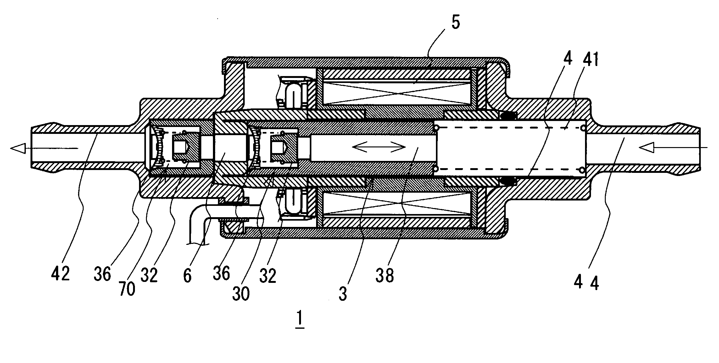
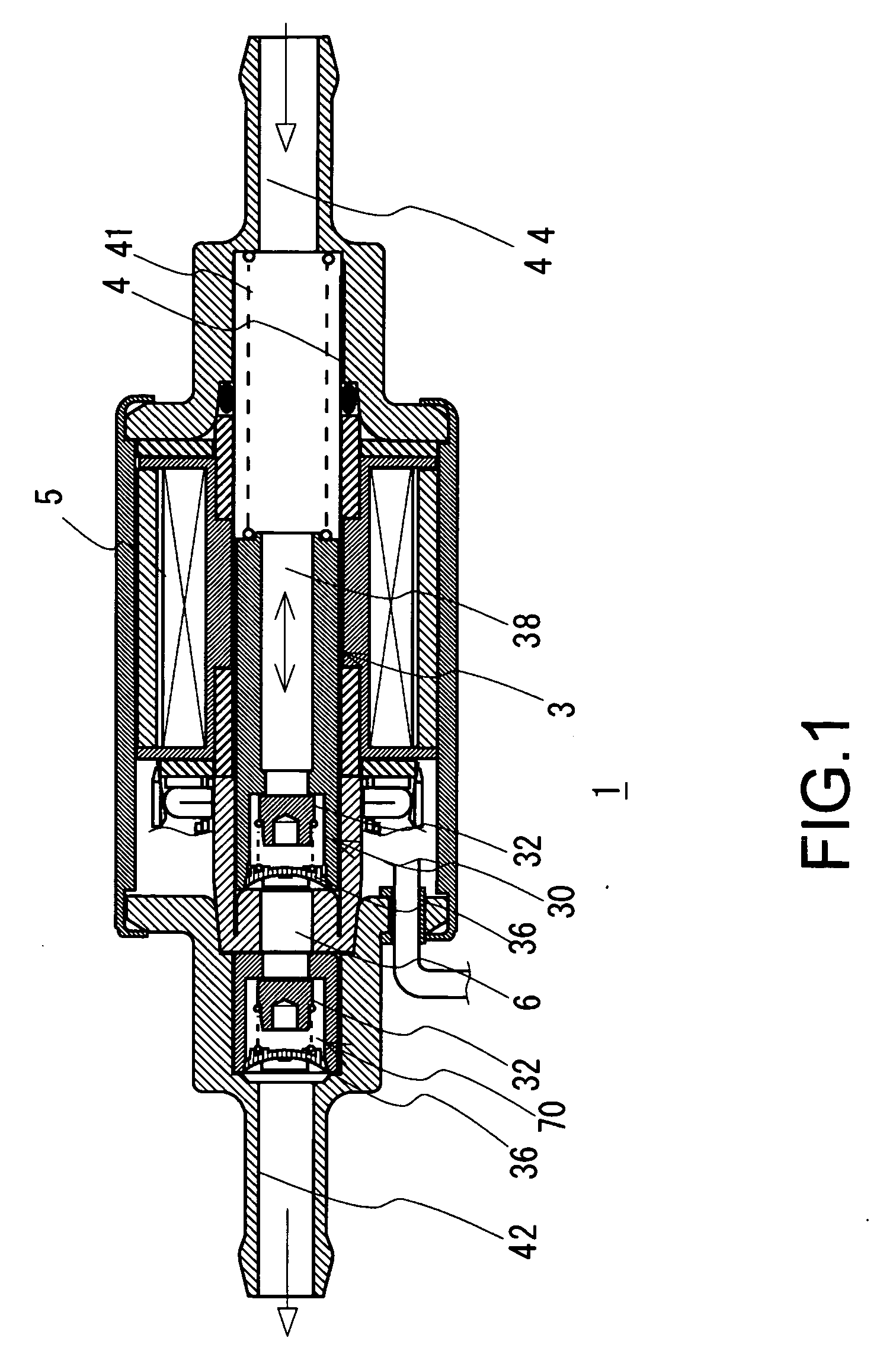
[0023]FIG. 1 shows a longitudinal cross sectional view of an electromagnetic fuel pump 1, for example, in the case that the present invention is used in a fuel supply system of a gasoline engine. The electromagnetic fuel pump 1 delivers a fuel corresponding to a gasoline reserved in a fuel tank (not shown) so as to supply it to an engine via a fuel piping by an injector, and is called as a so-called cylinder type electromagnetic fuel pump.

[0024]The electromagnetic fuel pump 1 is structured such that an electromagnetic coil 5 is provided around a cylinder 4, and a plunger 3 is slidably arranged in the cylinder 4 so as to be slidable in a horizontal direction in the drawing. A return spring 41 is arranged on a rear end side of the plunger 3 in a compressed state, and urges the plunger 3 toward the downward side, i.e., toward the left in the drawin...


PUM


Abstract

In a plunger type electromagnetic fuel pump, a cost reduction is achieved by reducing a number of parts in conjunction with a layout of a check valve and making a cleaning step after assembling unnecessary. In an electromagnetic fuel pump (1) which pressure-feeds a fuel from a pressurizing chamber (6) formed on the front side of a plunger (3) by controlling a current application to an electromagnetic coil (5) and repeating generation and elimination of a magnetic force so as to slidably reciprocate the plunger (3) arranged in a cylinder (4), spring retaining members (36) provided with spring guides (361) retaining proximal end sides of return springs (33) urging valve members (32, 32) of check valves (30, 70) forming the pressurizing chamber (6) integrally has fixing structures for fixing them to mounting positions, and are fixed without using the other fixing means.

Description

BACKGROUND OF THE INVENTION[0001]1. Field of the Invention[0002]The present invention relates to an electromagnetic fuel pump used for delivering a liquid fuel reserved in a fuel tank to a combustion apparatus, more particularly to a plunger type electromagnetic fuel pump.[0003]2. Description of Related Art[0004]Conventionally, a fuel pump has been employed as a fuel delivery means of a combustion apparatus such as an oil heater, an engine or the like, and as described in Japanese Unexamined Patent Publication No. 5-79452 and Japanese Unexamined Patent Publication No. 2002-39067, there has been generally widely spread a plunger type electromagnetic fuel pump which can achieve a stable fuel delivery and an accurate flow rate control by repeating generation and elimination of a magnetic force to slidably reciprocate a plunger urged by a return spring for pressurizing a fuel in a fuel passage.[0005]In the plunger type electromagnetic fuel pump, for example, as shown in a longitudinal c...

Claims


Application Information

Patent Timeline
Patent Type & Authority Applications(United States)
IPC IPC(8): F04B35/04
CPCF04B53/127F04B17/046
Inventor OHNISHI, KOUSUKE
Owner NIKKI CO LTD
Learn More