
Rate control process for a precursor delivery system

a control process and precursor technology, applied in the direction of coatings, chemical vapor deposition coatings, metallic material coating processes, etc., can solve the problems of difficult to deliver a predictable amount of precursor to the process chamber, difficult to control each of them, and non-uniform film thickness

Inactive Publication Date: 2008-02-21
APPLIED MATERIALS INC
View PDF75 Cites 69 Cited by
  • Summary
  • Abstract
  • Description
  • Claims
  • Application Information

AI Technical Summary

Benefits of technology

The present invention is an apparatus and system for controlling the delivery of a precursor from a vessel to a process chamber. The apparatus includes a valve to regulate the flow of carrier gas and a gas analyzer to measure the concentration of the precursor in the process gas. The system also includes a controller to calculate the mass flow rate of the precursor based on the concentration and volume flow rate of the process gas. The technical effect of this invention is to provide a reliable and accurate method for delivering precursors to a process chamber, ensuring consistent and safe operation.

Problems solved by technology

The rate of sublimation depends on a temperature of the precursor, a surface area of the precursor and how the carrier gas flows through the vessel, each of which may be very difficult to control.
Accordingly, it is often difficult to deliver a predictable amount of the precursor to the process chamber.
The difficulty in delivering a predictable amount of the precursor to the process chamber may lead to a number of problems.
One problem is that irregularities in the amount of solid precursor delivered to the process chamber may result in non-uniformities in film thickness that adversely affects wafer quality and acceptability.
This flow rate and pressure differential can cause problems to the deposition process, such as surface irregularities.
Furthermore, the thickness uniformity of a substrate surface is affected by not having independent control over the precursor delivery and the flow rate.

Method used


Image

  • Rate control process for a precursor delivery system
  • Rate control process for a precursor delivery system
  • Rate control process for a precursor delivery system

Examples


Embodiment Construction

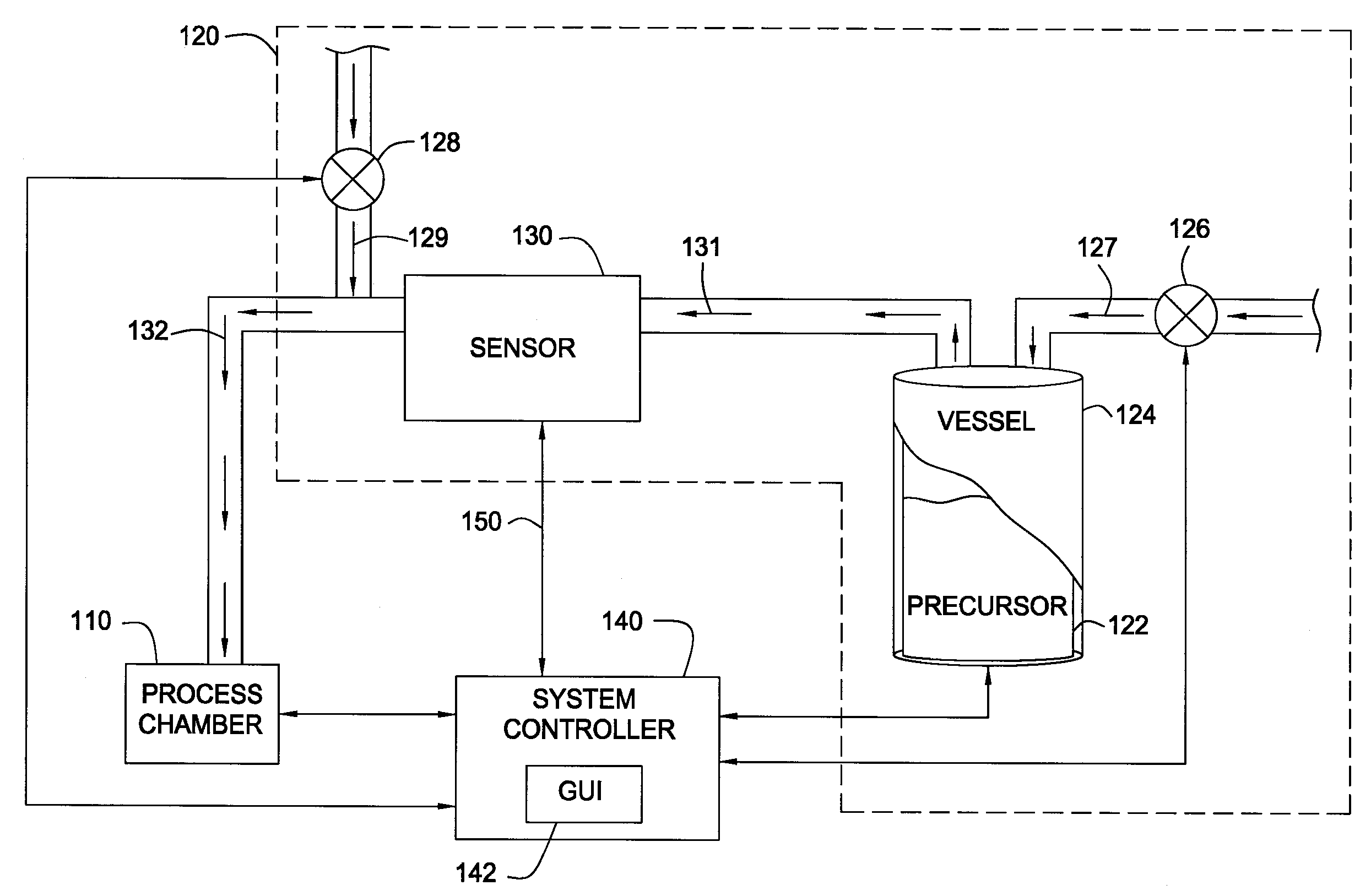
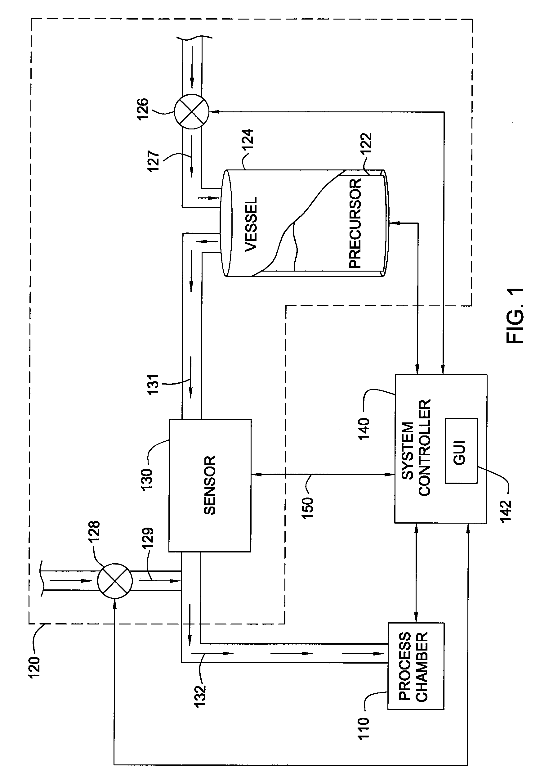
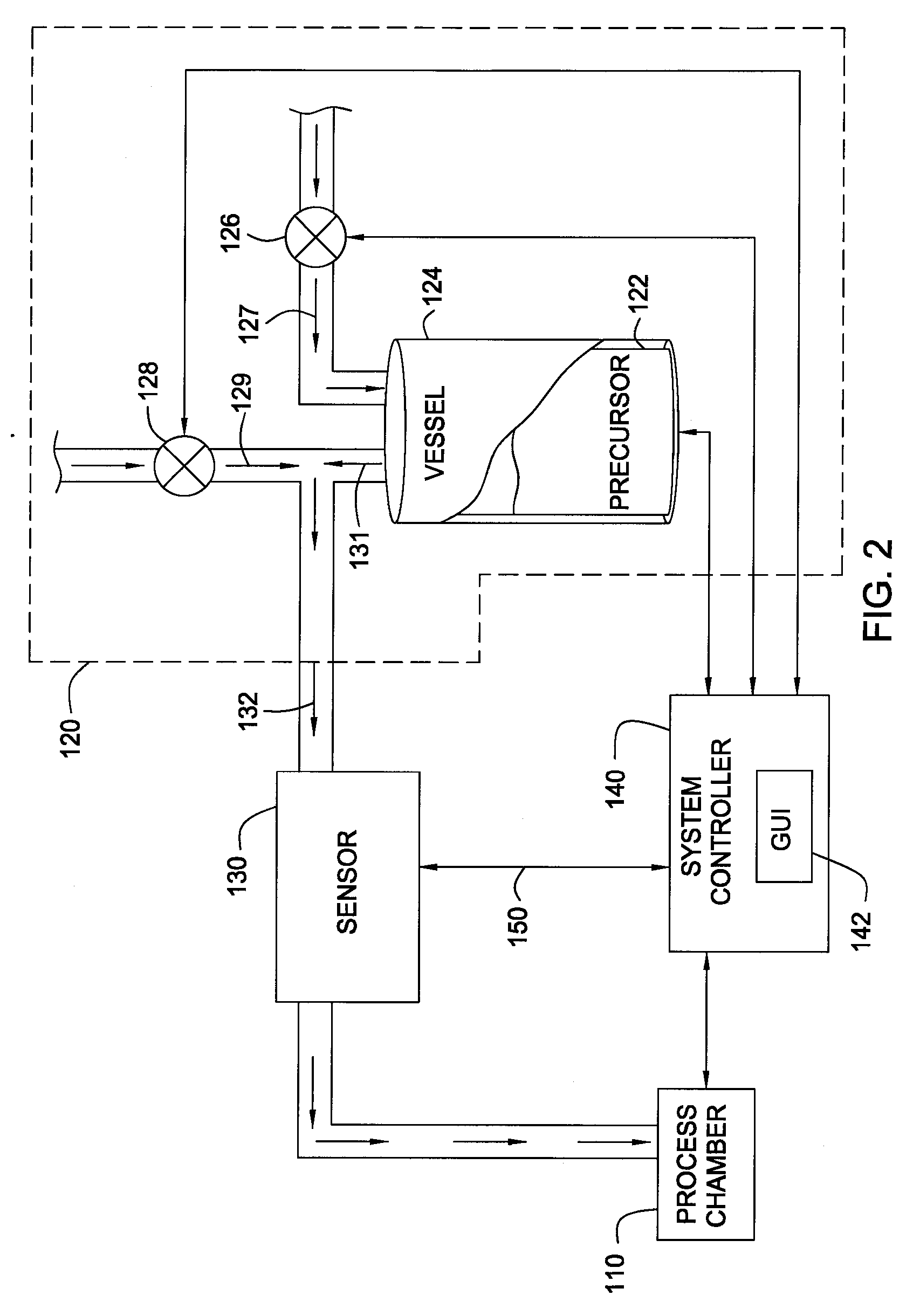
[0020]FIG. 1 illustrates an exemplary semiconductor processing system including a process chamber 110, a gas delivery system 120, and a sensor 130. The process chamber 110 may be any suitable semiconductor process chamber, such as a chemical vapor deposition (CVD) chamber, atomic layer deposition (ALD) chamber, plasma enhanced chemical vapor deposition (PECVD) chamber or etch chamber. Examples of suitable process chambers include, but are not limited to, the PRODUCER® series of CVD chambers, the SPRINT® and ENDURA® series of CVD / ALD chambers and the CENTURA® series of etch chambers, available from Applied Materials, Inc., located in Santa Clara, Calif.

[0021] The gas delivery system 120 transports a precursor 122 from a vessel 124 to the process chamber 110 via a process gas. Typically, the precursor 122 changes state from a solid to a gas (or vapor) in the vessel 124 by a sublimation process or the precursor 122 changes from a liquid to a gas by an evaporation process in the vessel...


PUM

PropertyMeasurementUnit
temperatureaaaaaaaaaa

Abstract

Embodiments of the invention provide a method for monitoring and controlling delivery of a precursor from an ampoule in a process chamber. In one embodiment, the method provides flowing a first carrier gas at a first flow rate through a vessel containing a chemical precursor to form a first precursor gas, combining a second carrier gas at a second flow rate and the first precursor gas to form a second precursor gas, measuring a concentration of the chemical precursor within the second precursor gas, and calculating a mass flow rate of the chemical precursor. In one example, a tantalum-containing film is deposited on a substrate during an atomic layer deposition process by heating an ampoule containing pentakis(dimethylamido) tantalum to a temperature within a range from about 60° C. to about 75° C., and forming a precursor gas by flowing a carrier gas through the ampoule.

Description

CROSS-REFERENCE TO RELATED APPLICATIONS [0001] This application is a divisional of U.S. Ser. No. 10 / 700,328 (APPM / 005190), filed Nov. 3, 2003, which is herein incorporated by reference in its entirety.BACKGROUND OF THE INVENTION [0002] 1. Field of the Invention [0003] Embodiments of the invention generally relate to semiconductor processing and other electronics fabrication, and particularly to controlling chemical precursor delivery to a processing chamber. [0004] 2. Description of the Related Art [0005] As integrated circuit (IC) density increases, the need for greater uniformity and process control regarding layer thickness rises. The IC fabricators make aggressive demands on the semiconductor processing industry to develop fabrication tools that provide for larger production yields while increasing the uniformity of layers deposited on substrates having increasingly larger surface areas. In response to these demands, various technologies have been developed to deposit layers on ...

Claims


Application Information

Patent Timeline
Patent Type & Authority Applications(United States)
IPC IPC(8): C23C16/44C23C16/448C23C16/52H01L21/285
CPCC23C16/4481H01L21/28556C23C16/52
Inventor CHEN, LINGKANG, PHILLIPGANGULI, SESHADRI
Owner APPLIED MATERIALS INC
Learn More