Viewing System for Control of Ptca Angiograms

a viewing system and angiogram technology, applied in the field of medical viewing systems, can solve the problems of not being able the step of positioning the stent is a very difficult step, and the visualization of the stent is difficult, so as to improve the visibility of the balloon or the stent, improve the visibility of the coronary artery, and improve the visualization of the artery.

Active Publication Date: 2008-02-21
KONINKLIJKE PHILIPS ELECTRONICS NV
View PDF7 Cites 47 Cited by
  • Summary
  • Abstract
  • Description
  • Claims
  • Application Information

AI Technical Summary

Benefits of technology

[0005] The artery walls, the guide-wire and the stent are mainly radio-transparent. Contrast agent may be diffuse through the coronary in order to visualize and localize the stenosed part of the coronary. When used, contrast agent must be introduced only in very small quantity during very small time duration because it presents toxicity for the patient. So, using contrast agent provides an improved visualization of the artery only during about a dozen of seconds. Besides, the contrast agent only permits of improving the visibility of the coronary, but does not permit of improving the visibility of the balloon or the stent.

Problems solved by technology

When used, contrast agent must be introduced only in very small quantity during very small time duration because it presents toxicity for the patient.
Besides, the contrast agent only permits of improving the visibility of the coronary, but does not permit of improving the visibility of the balloon or the stent.
Indeed, this step of positioning the stent is a very difficult step, due to bad condition of imaging.
Not only are the monorail, the balloon, the stent and the stenosed artery walls observed in noisy fluoroscopic images, but also they show low radiographic contrast that makes their visualization very difficult.
These movements make identification and localization of the balloon and the stent, which are Objects of Interest (OI) in fluoroscopic images, still more difficult to perform.
Moreover, these movements make zooming inefficient because the Objects of Interest may get out of the zoomed image frame.

Method used


Image

  • Viewing System for Control of Ptca Angiograms
  • Viewing System for Control of Ptca Angiograms
  • Viewing System for Control of Ptca Angiograms

Examples


Embodiment Construction

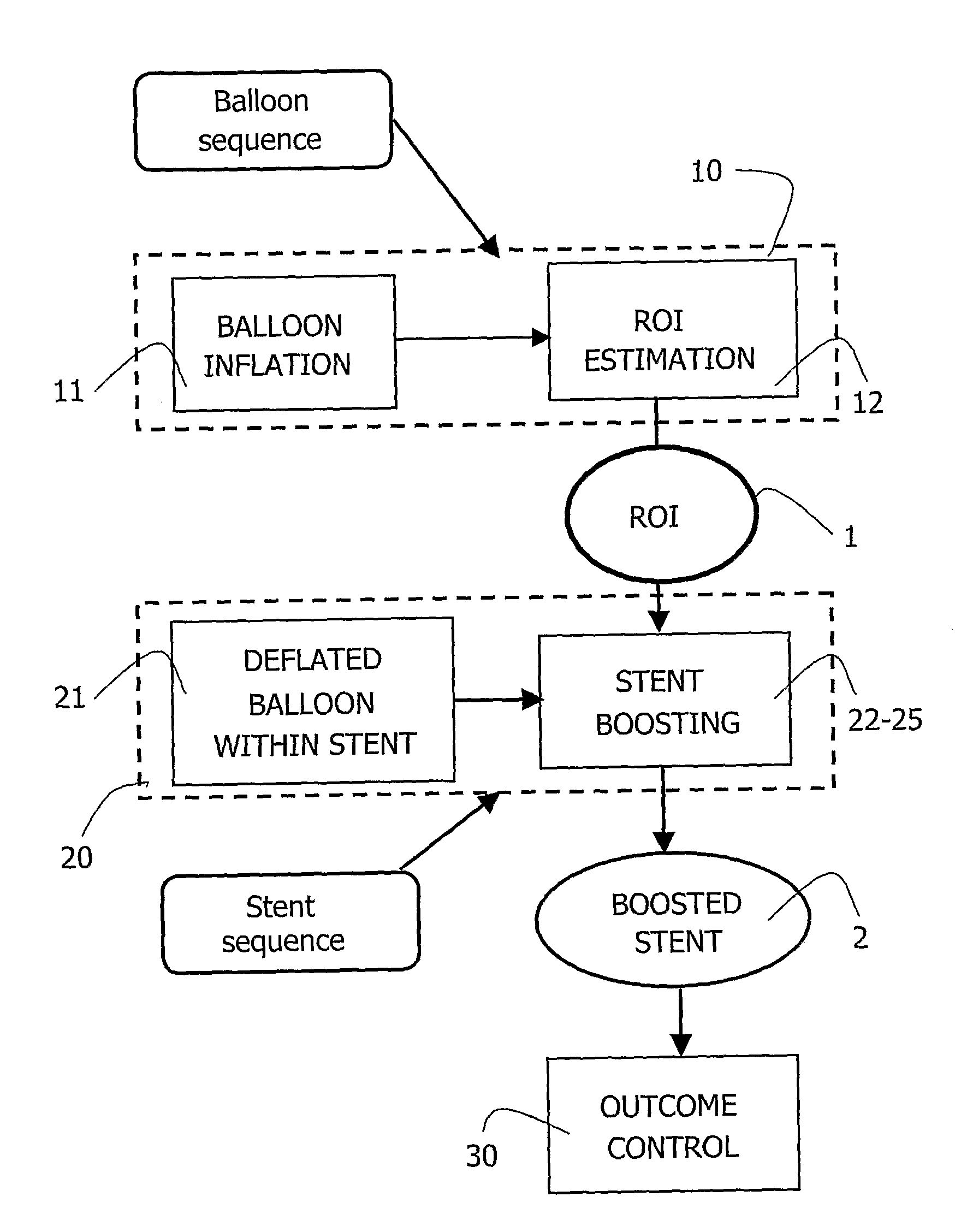
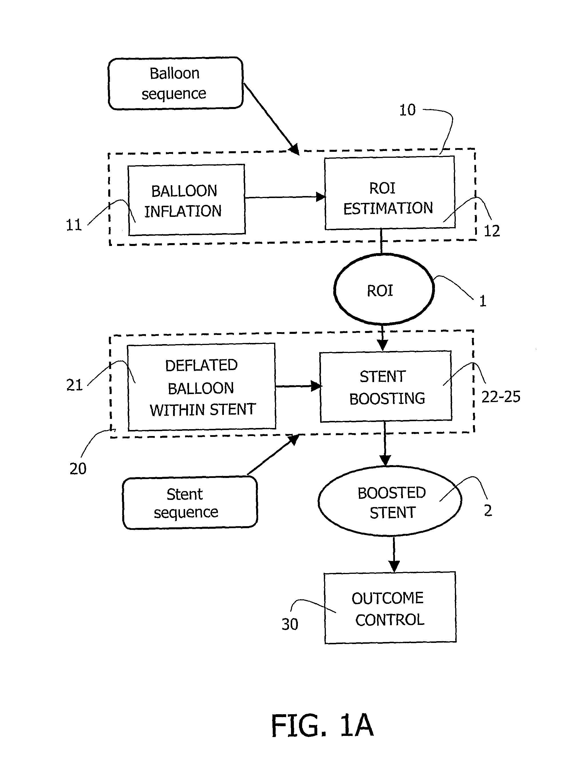
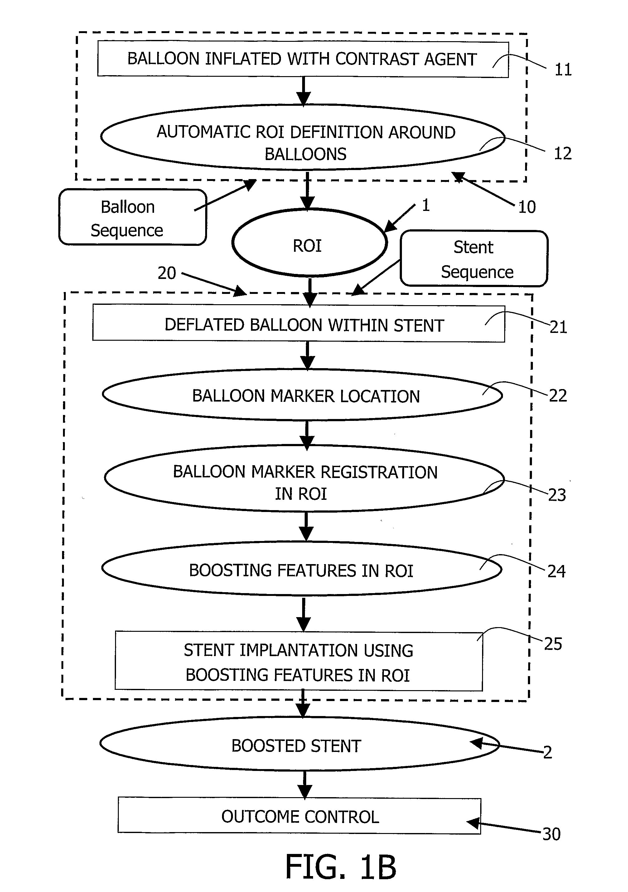
[0018] The invention relates to a real time viewing system, which has image processing means, for acquiring a sequence of noisy images and for on-line or off-line automatic definition of a ROI in the images of the sequence, based on automatic detection of structures in the images.

[0019] The invention further relates to the application of this automatic ROI to image processing means for registration of Objects of Interest, based on localization of specific structures of the ROI. The invention further relates to the application of this registered automatic ROI to image processing means for enhancement and occasionally zooming of the Objects of Interest in the ROI. The image processing means can be applied off-line. The viewing system and the image processing method of the invention are described hereafter in an example of application to the medical field of cardiology. In this application, the Objects of Interest (OI) are stent implantation tools such as balloons, balloon markers or ...


PUM


Abstract

A medical viewing system for processing and displaying a sequence a sequence of medical angiograms representing a balloon, moving in an artery, this system comprising extracting means for automatically extracting balloon image data in a phase of balloon expansion, and computing means for automatically defining and storing coordinates of a Region of Interest (ROI) based on the expanded balloon image data, located around the expanded balloon; and display means for displaying the images. Contrast agent may be used as agent of balloon expansion. The system may have means to detect and keep track of balloon markers and means to look around those markers for further balloon image data extraction.

Description

FIELD OF THE INVENTION [0001] The invention relates to a medical viewing system having means for detecting objects of interest in a sequence of medical images. The invention particularly relates to a viewing system, which has image processing means and image display means, for accurate control of the positioning of medical tools in an artery, in a sequence of angiograms. The invention finds for example its application for accurate control of the positioning of a stent in a coronary in an operation of “Percutaneous Transluminal Coronary Angioplasty” (PTCA). The invention also relates to an image processing method to be used in said system. The invention further relates to a medical examination apparatus coupled to such a system. BACKGROUND OF THE INVENTION [0002] A method for extracting stents in medical images is already known from the publication entitled “Deformable Boundary Detection of Stents in Angiographic Images”, by Ioannis Kompatsiaris et alii, in IEEE TRANSACTIONS ON MEDIC...

Claims


Application Information

Patent Timeline
Patent Type & Authority Applications(United States)
IPC IPC(8): A61B5/00A61B6/00A61B6/12A61B17/22A61B19/00A61F2/82A61F2/958
CPCA61B6/12A61B6/469A61B6/504A61F2/958A61B2017/22051A61F2/82A61B19/54A61B90/39
Inventor RONGEN, PETER MARIA JOHANNESFLORENT, RAOULSTEGEHUIS, HERMAN
Owner KONINKLIJKE PHILIPS ELECTRONICS NV
Why Eureka
Try Eureka