Liquid Transfer Device for Medical Dispensing Containers

a technology of liquid transfer device and medical dispensing container, which is applied in the field of liquid transfer device, can solve the problems of affecting the properties and stability of said suspension, the relative long storage time of the reconstituted suspension may pose some problems, and the amount of air may be a little too much

Inactive Publication Date: 2008-02-21
BRACCO RES USA
View PDF22 Cites 144 Cited by
  • Summary
  • Abstract
  • Description
  • Claims
  • Application Information

AI Technical Summary

Benefits of technology

[0018] when said device cooperates with the container in steady state conditions, said valve substantially prevents a gaseous exchange between said container and the external ambient.
[0020] Advantageously the transfer device comprises a filter associated to the second conduit, for protecting the content of the vial against microbial contamination during liquid withdrawal. Preferably, said filter also prevents the fluid to flow out from the container into the external ambient. Said filter is preferably a liquid impermeable / gas permeable filter. More preferably it is a hydrophobic filter.

Problems solved by technology

As observed by the Applicant, such a relatively long storage time of the reconstituted suspension may however pose some problems, particularly in connection with a possible exchange between the gas contained inside the container and the outer atmosphere air.
682 530), an excessive amount of air may nevertheless negatively affect said properties and stability.
Furthermore, the above undesirable gas / air exchange may similarly take place also when the transfer device is connected to the vial and left in place for a certain time, without connecting a syringe thereto and / or injecting a liquid into the vial.
No means are foreseen in said prior art valves for allowing / controlling overpressure gas discharge upon liquid injection.

Method used


Image

  • Liquid Transfer Device for Medical Dispensing Containers
  • Liquid Transfer Device for Medical Dispensing Containers
  • Liquid Transfer Device for Medical Dispensing Containers

Examples


example 1

Measure of Gas Exchange with Different Valves

[0057] 18 vials (each having an internal volume of about 11 cm3) are filled with SF6 gas at room temperature up to about atmospheric pressure and sealed with a rubber stopper.

[0058] The vials are divided in three groups of six vials each and the stopper of each vial is then pierced with a liquid transfer device as indicated hereinafter:

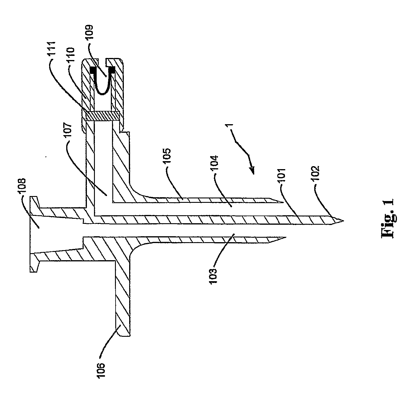
[0059] Device 1a (comparative): device of FIG. 1, with clogged liquid duct and without valve 109;

[0060] Device 1b: device of FIG. 1, with clogged liquid duct and valve Vernay 5033;

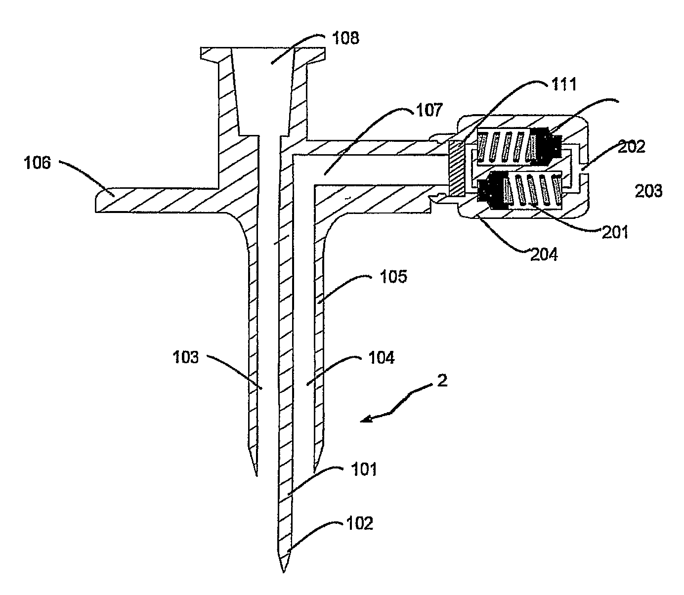
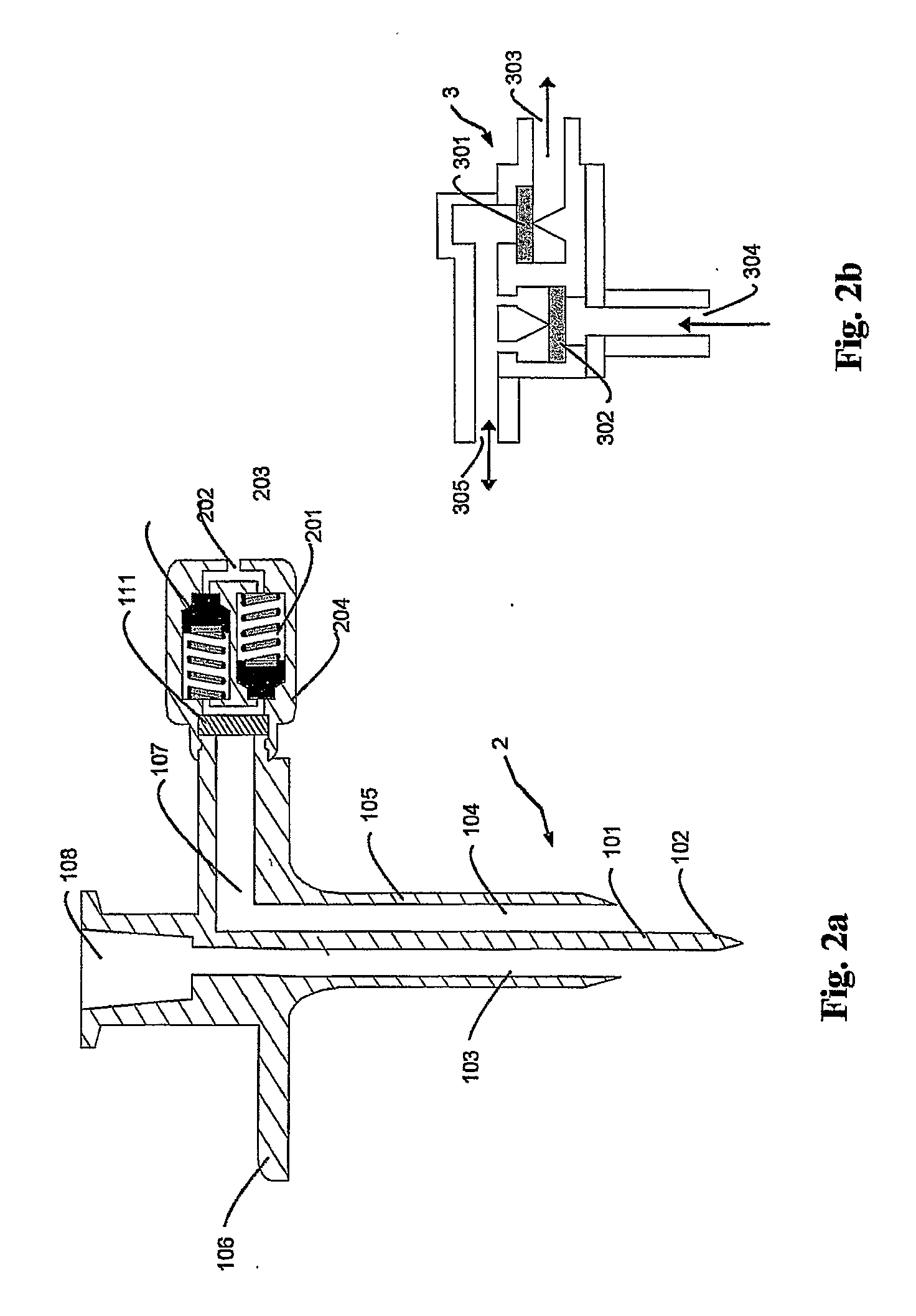
[0061] Device 1c: device of FIG. 2, with clogged liquid duct and two valves Halkey-Roberts 246302001.

[0062] For all the devices, the diameter of the ventilation duct is of about 1.1 mm.

[0063] Groups of six devices for each type are used for piercing respective groups of six vials. The six vials of each group are then used to determined the content of air penetrated therein as a function of time, by removing the device from ...

example 2

Measure of Pressure Variation During Liquid Injection

[0065] To measure the pressure variation inside a vial upon liquid injection and withdrawal by using a transfer device according to example 1b, the following set-up has been used.

[0066] A syringe filled with saline solution is attached to a duct comprising a calibrated differential pressure transducer (COBE® pressure sensor Ref: #041-500-5003) and then attached to the liquid duct of the device according to example lb. The whole assembly is then inserted in a vial as described in example 1. The syringe plunger is moved at constant speed to allow a substantially constant injection rate (1 ml / sec) in the vial, for a total volume of 2 ml. FIG. 6a shows the variation of pressure inside the vial as a function of time: (61) correspond to the injection step and (62) to the intermediate steady state. The injected solution is left in the vial for about 50 seconds. Afterwards, the vial is inverted and the solution is withdrawn therefrom. F...


PUM


Abstract

Liquid transfer device to be used to transfer a liquid into or from a dispensing container, particularly a medical dispensing container like a vial for diagnostic agents and kit comprising a vial, a syringe and a device of the aforementioned type. The transfer device comprises a valve which substantially limits the gaseous exchange between the inside of a vial and the external ambient, when the device is connected to the vial in steady state conditions.

Description

TECHNICAL FIELD [0001] The invention relates to a liquid transfer device to be used to transfer a liquid into or from a medical dispensing container, such as a vial for diagnostic agents, and particularly to a pharmaceutical kit comprising said device and said container. BACKGROUND OF THE INVENTION [0002] Medical dispensing containers made of glass or polymeric materials, the walls of which are non-collapsible, typically require an air inlet when a medical fluid is withdrawn therefrom, to prevent the formation of vacuum therein. Typically, vials containing a medical fluid are closed by rubber stoppers which are pierced by a spike of a transfer device having a duct for the passage of the medical fluid and a ventilation duct. Examples of devices comprising a liquid fluid duct and a ventilation duct are disclosed, for instance, in U.S. Pat. No. 3,797,521, U.S. Pat. No. 4,262,671, U.S. Pat. No. 4,623,343, U.S. Pat. No. 4,857,068, U.S. Pat. No. 5,041,106, and U.S. Pat. No. 6,139,534. [00...

Claims


Application Information

Patent Timeline
Patent Type & Authority Applications(United States)
IPC IPC(8): A61B19/00
CPCA61M2005/1623A61M5/162
Inventor JAKOB, LAURENTRIVAS, FREDERIC
Owner BRACCO RES USA
Why Eureka
Try Eureka