Method for fabricating antenna units

a technology of antenna units and fabrication methods, which is applied in the manufacture of printed circuits, waveguide devices, printed electric components, etc., can solve the problems of time-consuming and expensive methods, bringing the product a relatively large weight, and a relatively high cost, so as to achieve low cost, low cost, and high efficiency.

Inactive Publication Date: 2008-02-28
ADVANCED CONNECTEK INC
View PDF7 Cites 29 Cited by
  • Summary
  • Abstract
  • Description
  • Claims
  • Application Information

AI Technical Summary

Benefits of technology

[0008]In view of the forgoing, this invention provides a method of fabricating antenna units, which allows the manufacturer to conduct a fabricating process in high efficiency, low cost and little pollution in a continuous manner, and also allows each antenna to have a fall receiving performance due to the precision of the process of the method.

Problems solved by technology

The method not only is time-consuming and costly but also brings the product a relatively large weight.
Moreover, since the electromagnetic wave penetrate into the surface of the antenna by merely several microns in high-frequency applications, using a relatively thick metal sheet to form an antenna circuit not only brings the product a relatively large weight and a relatively high cost but also causes a waste.
However, using conductive silver paste to print an antenna circuit not only costs much, but also makes a low yield and a receiving performance of merely about 50% for the product.
Printing an antenna circuit with a conductive copper paste costs less, but the yield is still low and the receiving performance is merely about 40% for the product.
The etching-based method makes a quite high yield and a receiving performance near 100%, but causes environmental pollution and costs much.
In addition, fabricating an antenna circuit with electrodeless copper plating makes a relatively higher yield and a receiving performance about 90%, but causes environmental pollution and costs much.

Method used


Image

  • Method for fabricating antenna units
  • Method for fabricating antenna units
  • Method for fabricating antenna units

Examples


first embodiment

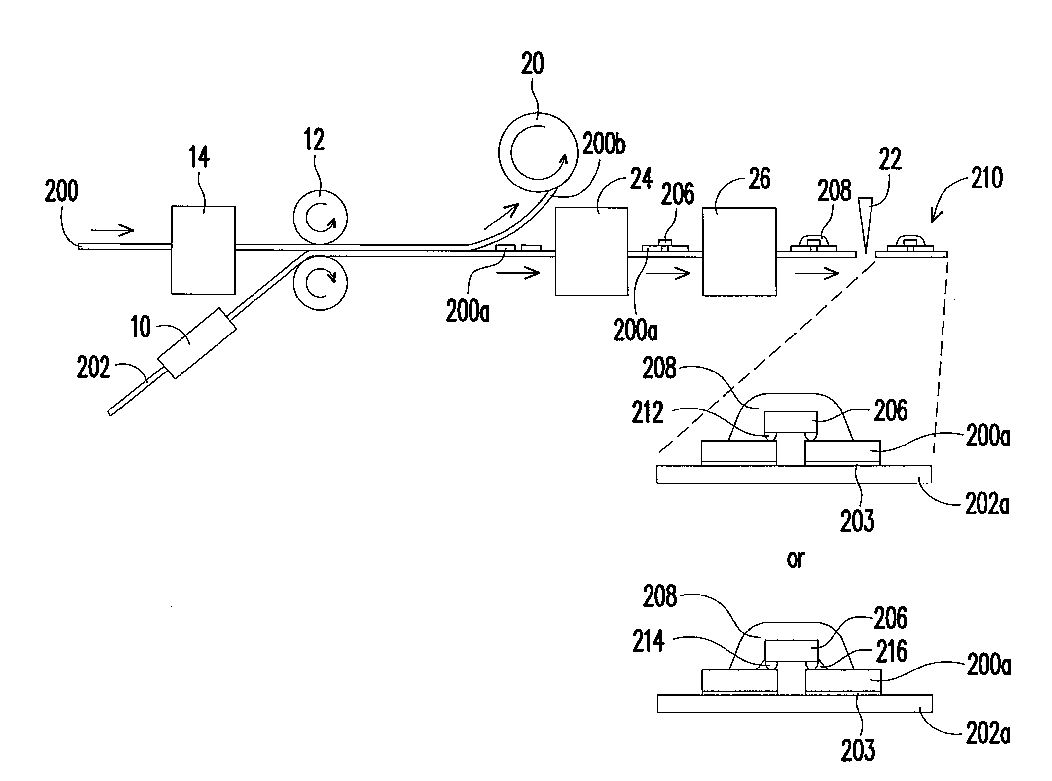
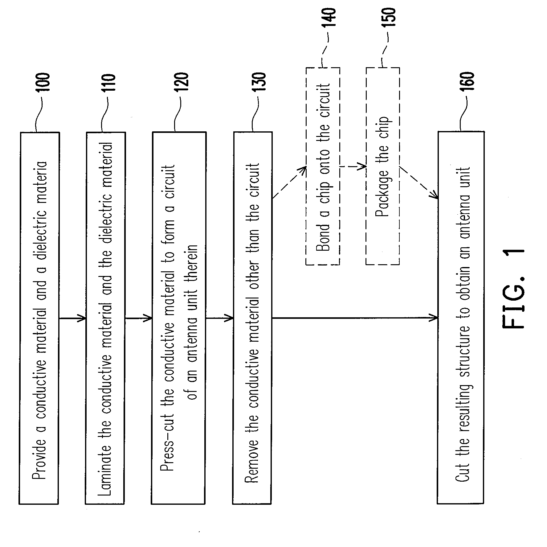
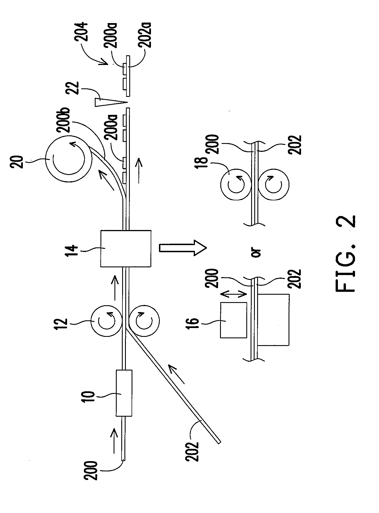
[0021]FIG. 1 is a flow chart illustrating the fabrication of an antenna unit in a method of fabricating antenna units according to the first embodiment of this invention. By establishing a continuous processing mechanism of multiple antenna units based on the steps of the fabrication of one antenna unit, multiple antenna units can be fabricated continuously. FIGS. 2 and 3 illustrate two examples of such a mechanism respectively.

[0022]Referring to FIGS. 1 and 2, a conductive material 200 and a dielectric material 202 are provided (step 100) in a continuous manner. Each of the materials 200 and 202 is preferably in the form of a contiguous film or tape, which may be stored in the form of a roll before being provided for the convenience of storage and continuous use.

[0023]Specifically, the conductive material can be a film of a metal or a metal alloy, or an insulating film coated with a metal or a metal alloy. The metal or metal alloy may include at least one material selected from the...

second embodiment

[0033]FIG. 4 is a flow chart illustrating the fabrication of an antenna unit in a method of fabricating antenna units according to the second embodiment of this invention. The second embodiment is different from the first embodiment in that the order of the lamination operation (420) and press-cutting operation (410) is reversed. The steps 400, 430, 440, 450 and 460 are similar to the steps 100, 130, 140, 150 and 160, respectively, and are therefore not described again. FIGS. 5 and 6 show two examples of such a method of fabricating antenna units. Since FIG. 5 / 6 is different from FIG. 2 / 3 merely in that the press-cutting means 14 is disposed before rather than after the two opposite rollers 12, the details of the operations corresponding to the steps 400-460 are similar to those of the operations corresponding to the steps 100-160 that have been mentioned in the first embodiment and are therefore not described again.

[0034]Nevertheless, in the second embodiment where the conductive m...


PUM

PropertyMeasurementUnit
conductiveaaaaaaaaaa
insulatingaaaaaaaaaa
dielectricaaaaaaaaaa

Abstract

A method of fabricating antenna units is described, including providing a conductive material and a dielectric material, laminating the conductive material and the dielectric material, press-cutting the conductive material to form therein circuits of a plurality of antenna units, removing the conductive material other than the circuits to form a composite structure, and cutting the composite structure to obtain the antenna units. Before each antenna unit is obtained through cutting, a chip may be bonded onto the circuit thereof and then packaged so that an RFID tag is obtained after the cutting. The method allows the manufacturer to conduct a fabricating process in high efficiency, low cost and little pollution in a continuous manner, and also allows each antenna to have a full receiving performance due to the precision of the process.

Description

CROSS-REFERENCE TO RELATED APPLICATION[0001]This application claims the priority benefit of Taiwan application serial no. 95131346, filed Aug. 25, 2006. All disclosure of the Taiwan application is incorporated herein by reference.BACKGROUND OF THE INVENTION[0002]1. Field of the Invention[0003]This invention relates to fabrication of radio-frequency identification (RFID) devices, and more particularly to a method for fabricating antenna units, which allows the manufacturer to conduct a fabricating process in high efficiency, low cost and little pollution in a continuous manner and also allows each antenna to have a full receiving performance due to the precision of the process.[0004]2. Description of the Related Art[0005]A conventional method of fabricating an antenna unit includes stamp-cutting a metal sheet to obtain an antenna circuit and manually bonding the same onto a dielectric sheet. The method not only is time-consuming and costly but also brings the product a relatively lar...

Claims


Application Information

Patent Timeline
Patent Type & Authority Applications(United States)
IPC IPC(8): H01P11/00
CPCH05K1/165Y10T29/49016H05K2203/1545H05K3/041
Inventor LIN, SHUN-TIANLIN, CHAO-TSUNG
Owner ADVANCED CONNECTEK INC
Why Eureka
Try Eureka