

Control system and process for wastewater treatment
a control system and wastewater technology, applied in the field of wastewater treatment, can solve the problems of affecting the continual flow of wastewater, affecting the effect of wastewater treatment, and often affecting the flow of wastewater, so as to achieve the effect of effectively positioning the resultant floc and accelerating the drainage of water from said flo
- Summary
- Abstract
- Description
- Claims
- Application Information
AI Technical Summary
Benefits of technology
Problems solved by technology
Method used
Image

Examples
Embodiment Construction
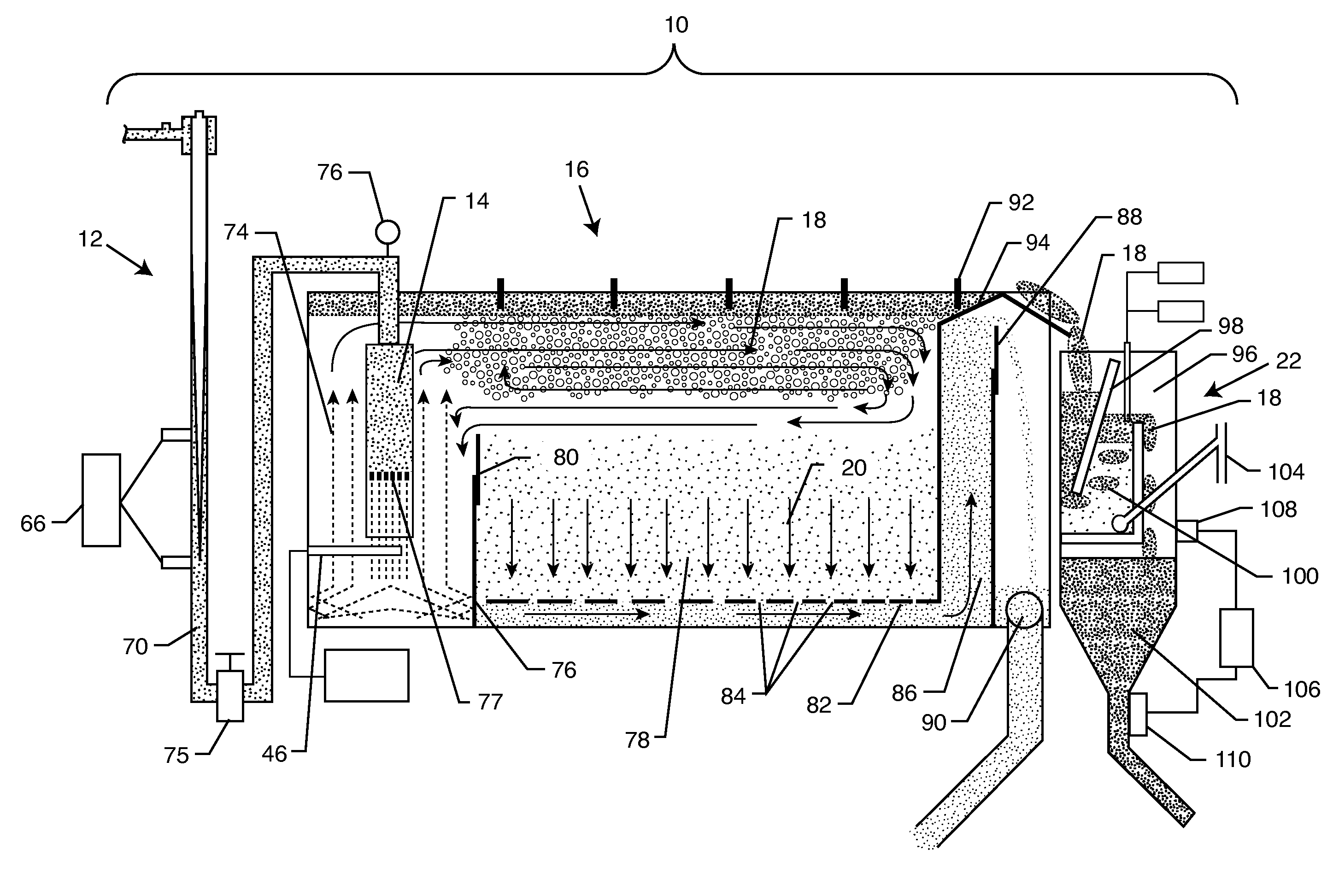
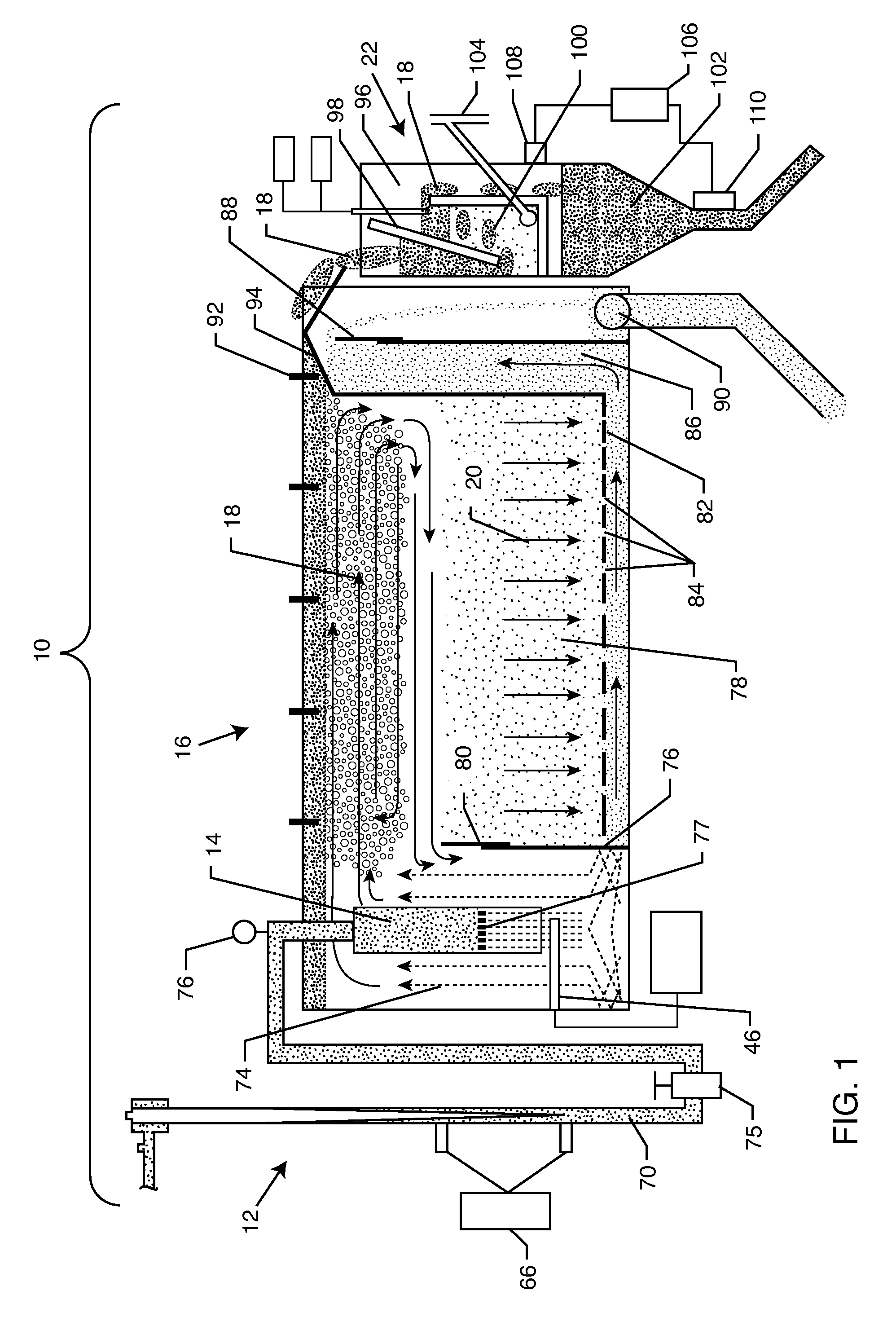
[0029]As shown in the exemplary drawings for purposes of illustration, the present disclosure for a wastewater treatment control system and process is referred to generally by the reference numeral 10. Turning now to the representative figures in the specification, FIG. 1 illustrates the wastewater treatment control system 10 having a mixer 12 fluidly coupled to a nucleation chamber 14 which is disposed within a flotation tank 16. The mixer 12, as will be more fully described herein, is particularly designed to mix chemical additives, gas, and the like into the contaminated liquid. The gas is entrained in the liquid at a small size to adhere to solid particles and flocculants. Thereafter, as the liquid passes through the nucleation chamber 14, the bubbles enlarge in size and raise the floc and solid contaminants toward the surface of the flotation tank 16. Eventually, the floated particles form a sludge or froth 18, while the decontaminated liquid 20 sinks to the bottom of the flota...
PUM
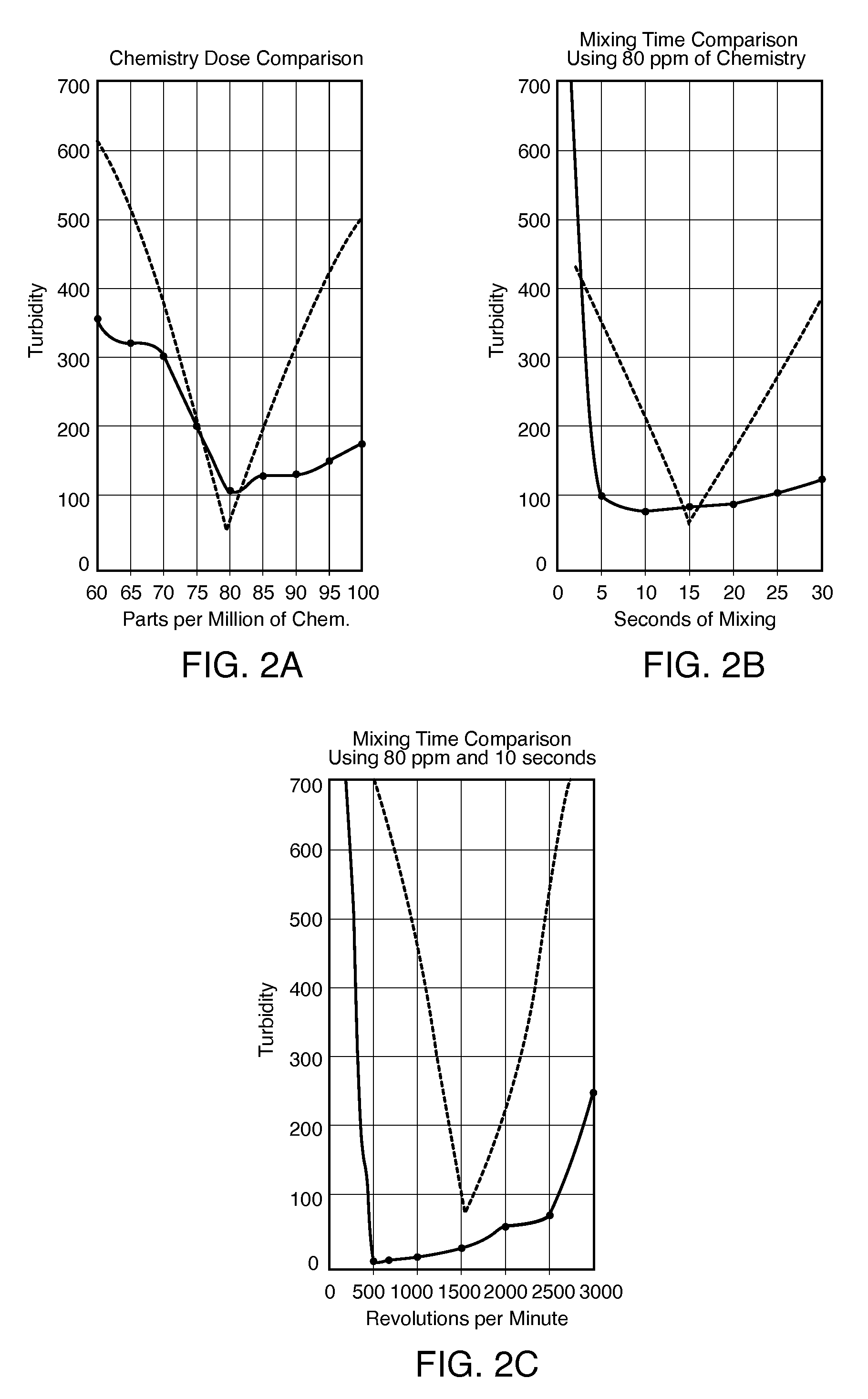
| Property | Measurement | Unit |
|---|---|---|
| diameter | aaaaa | aaaaa |
| nucleation pressures | aaaaa | aaaaa |
| pH | aaaaa | aaaaa |
Abstract
Description
Claims
Application Information