High Frequency Heating Apparatus

a heating apparatus and high frequency technology, applied in the direction of dc-ac conversion without reversal, electric/magnetic/electromagnetic heating, sustainable buildings, etc., can solve the problems of shortening the cooking time, affecting the efficiency of the heating apparatus, and consuming as much as 2000 watts of the microwave oven, so as to achieve the effect of easy formation of frequency modulation waveform

Inactive Publication Date: 2008-02-28
PANASONIC CORP
View PDF3 Cites 48 Cited by
  • Summary
  • Abstract
  • Description
  • Claims
  • Application Information

AI Technical Summary

Benefits of technology

[0018] With a high frequency heating apparatus according to the invention, an inverter operating frequency in each phase of the commercial power supply is variable, and it is possible to embody a current waveform in which a harmonic component is small, by enlarging the operating frequency in the range from 0° to 90°. It is possible to form a frequency modulation waveform in which the degree of freedom i

Problems solved by technology

In addition, the microwave oven consumes as much as 2000 watts for the sake of shortening the cooking time.
As a result, an absolute value of the current is also increased, and it makes difficul

Method used


Image

  • High Frequency Heating Apparatus
  • High Frequency Heating Apparatus
  • High Frequency Heating Apparatus

Examples


first embodiment

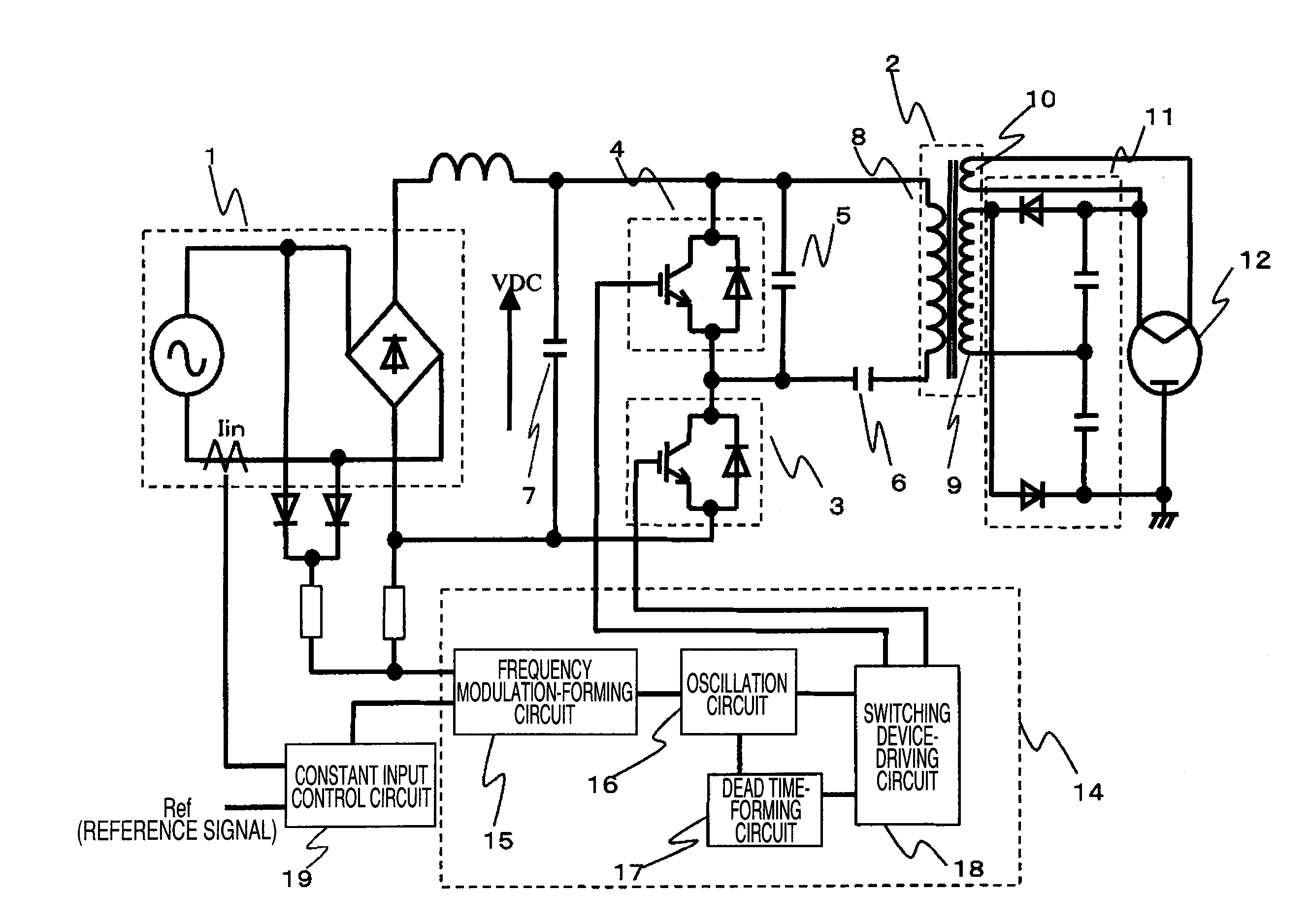
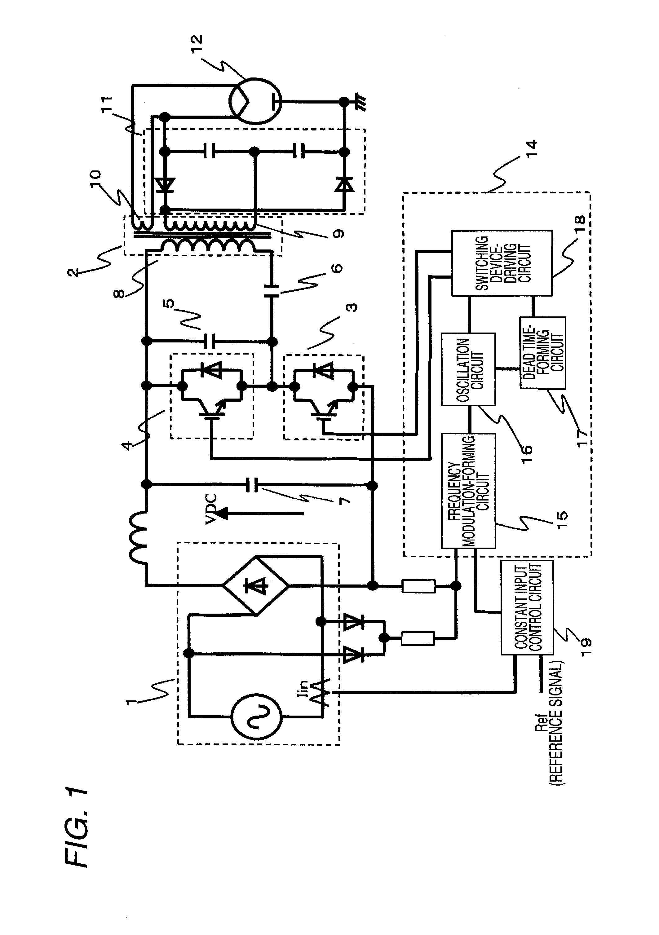
[0069]FIG. 1 is a diagram illustrating a circuit configuration for driving a magnetron according to the invention. A DC power supply 1, a leakage transformer 2, a first semiconductor switching element 3, a second semiconductor switching element 4, a first capacitor 5, a second capacitor 6, a third capacitor 7, a driving control IC unit 14, a full-wave voltage doubler rectifcation circuit 11, and a magnetron 12 constitute the overall circuit. The description of the overall circuit configuration will be omitted since it is the same as that shown in FIG. 12.

[0070] In the driving control IC unit 14 for driving the semiconductor switching elements 3 and 4, a frequency modulation-forming circuit 15 forms a frequency modulation waveform using a resistance divided waveform on the basis of the voltage of a commercial power supply. The frequency modulation-forming circuit 15 performs a feedback control receiving signals from a constant input control circuit 19 so as to obtain the desired inp...

second embodiment

[0074]FIG. 4 is an exemplary diagram illustrating the frequency modulation-forming circuit 15 in detail shown in FIG. 1. The fixed voltage obtained in the resistors 151 and 152 becomes the upper limit on the basis of the voltage dividing waveform after the commercial power supply is rectified (Aspects 3 and 8). FIG. 6(a) shows the frequency modulation waveform in this time. On the basis of the commercial power rectifying voltage-dividing waveform indicated by the dashed line, the upper limit value is given as indicated by the solid line. Next, when diodes 158 and 159, and resistors 155, 156, and 157 are provided to an upper clamp shown in FIG. 5, the frequency modulation waveform can be formed as a curved line with some variation from reference voltage given in the resistors 151 and 152, not the fixed value (Aspect 9). FIG. 6(b) shows the curved line indicated by the solid line. In addition, in order to determine the upper limit as a variable value not a fixed value, an increase or ...

third embodiment

[0075]FIG. 7 is an exemplary diagram illustrating the frequency modulation-forming circuit 15 shown in FIG. 1. The lower limit value is restricted to the fixed voltage given from the resistors 153 and 154 on the basis of a voltage-dividing waveform after rectifying the commercial power supply. In this case, the lower limit clamp means the lower limit value corresponding to the lowest frequency restriction (Aspects 4, 5, 12, and 16). FIG. 9(a) shows the frequency modulation waveform in this case, and the lower limit (lower limit corresponding to the lowest frequency) indicated by the solid line is denoted on the basis of the commercial power rectifying voltage-dividing waveform indicated by the dashed line. Next, when a resistor is provided to the lower limit clamp shown in FIG. 8, the frequency modulation waveform can be formed as a curved line with some variation from the reference voltage obtained in the resistors 153 and 154 not a fixed value (Aspect 13). FIG. 9(b) shows the curv...


PUM


Abstract

The invention relates to a high frequency heating apparatus that drives a magnetron such as a microwave, and provides a frequency modulation method of preventing harmonic current occurring due to a high frequency switching operation.
When a driving signal is transmitted in order to drive a first semiconductor switching element (3) and a second semiconductor switching element (4), an inverter operating frequency in the every phase of a commercial power supply is provided as a frequency difference (inclination) of the phase range from 0° to 90° using a triangular wave-forming circuit in an oscillation circuit (16). A modulation waveform for a frequency modulation control is formed, configuring an upper limit clamp, a lower limit clamp, a lower limit value corresponding to the lowest frequency in a frequency modulation-forming circuit (15) on the basis of a commercial power rectifying voltage-dividing waveform after rectification. By combining these optimally, it is possible to prevent the harmonic current from occurring while forming the frequency modulation waveform handling several non-uniformities such as constants of major inverter circuit components or a power supply (Vcc) of a driving control IC unit (14).

Description

TECHNICAL FIELD [0001] The present invention relates to a control for suppressing generation of harmonic current components in a field of a high frequency heating apparatus such as a microwave oven which performs a dielectric heating process by driving a magnetron. BACKGROUND ART [0002] A power supply used in cooking appliances based on high-frequency heating such as a microwave oven used at home has been required to be small in size and light in weight owing to the nature of the cooking appliances. It is desirable that the space for accommodating the power supply is small in order to easily carry it and enlarge a cooking space in the kitchen. For this reason, the microwave oven is becoming smaller and lighter and being manufactured at low cost with employing a switching power supply. As a result, the power supply outputs a current waveform containing lots of harmonic components which are generated by a switching operation of the power supply. In addition, the microwave oven consume...

Claims


Application Information

Patent Timeline
IPC IPC(8): H05B6/74H02M7/48H02M7/538H05B6/66
CPCY02B40/143H05B6/685Y02B40/00
Inventor MORIYA, HIDEAKISUENAGA, HARUOSAKAI, SHINICHISHIROKAWA, NOBUOKINOSHITA, MANABU
Owner PANASONIC CORP
Why Eureka
Try Eureka