
Linear actuator system and method

Active Publication Date: 2008-02-28
EXLAR CORP
View PDF22 Cites 50 Cited by
  • Summary
  • Abstract
  • Description
  • Claims
  • Application Information

AI Technical Summary

Benefits of technology

[0008] According to one aspect of the present invention, the speed and torque changes happen automatically when the load requires high force, are mechanically implemented, do not require elaborate electronic controls (but may use them for enhanced performance), and do not require anticipating the change and / or a significant amount of time to engage or sequence the two motors. The system and method of the present invention responsively reacts to sudden or gradual changes in force required by the load on the linear actuator and provides motion occurring in either direction at any speed. Additional servo controls, or other controls, may be added to further enhance the performance of the system, but are not required for the basic system of the invention to work.

Problems solved by technology

A high power motor will generally cost more and be larger than a lower power motor, and if drive electronics are required, their cost and size will also typically be greater as power is increased.
These solutions can require expensive or complicated mechanisms, and often require active electronic control.

Method used


Image

  • Linear actuator system and method
  • Linear actuator system and method
  • Linear actuator system and method

Examples


Embodiment Construction

.

[0014] The advantages and features which characterize the invention are pointed out with particularity in the claims annexed hereto and forming a part hereof. For a better understanding of the invention, however, reference should be had to the drawings which form a part hereof and to the accompanying descriptive matter, in which there is illustrated and described a preferred embodiment of the invention.

BRIEF DESCRIPTION OF THE DRAWINGS

[0015] In the drawings in which like elements are identified with the same designation numeral:

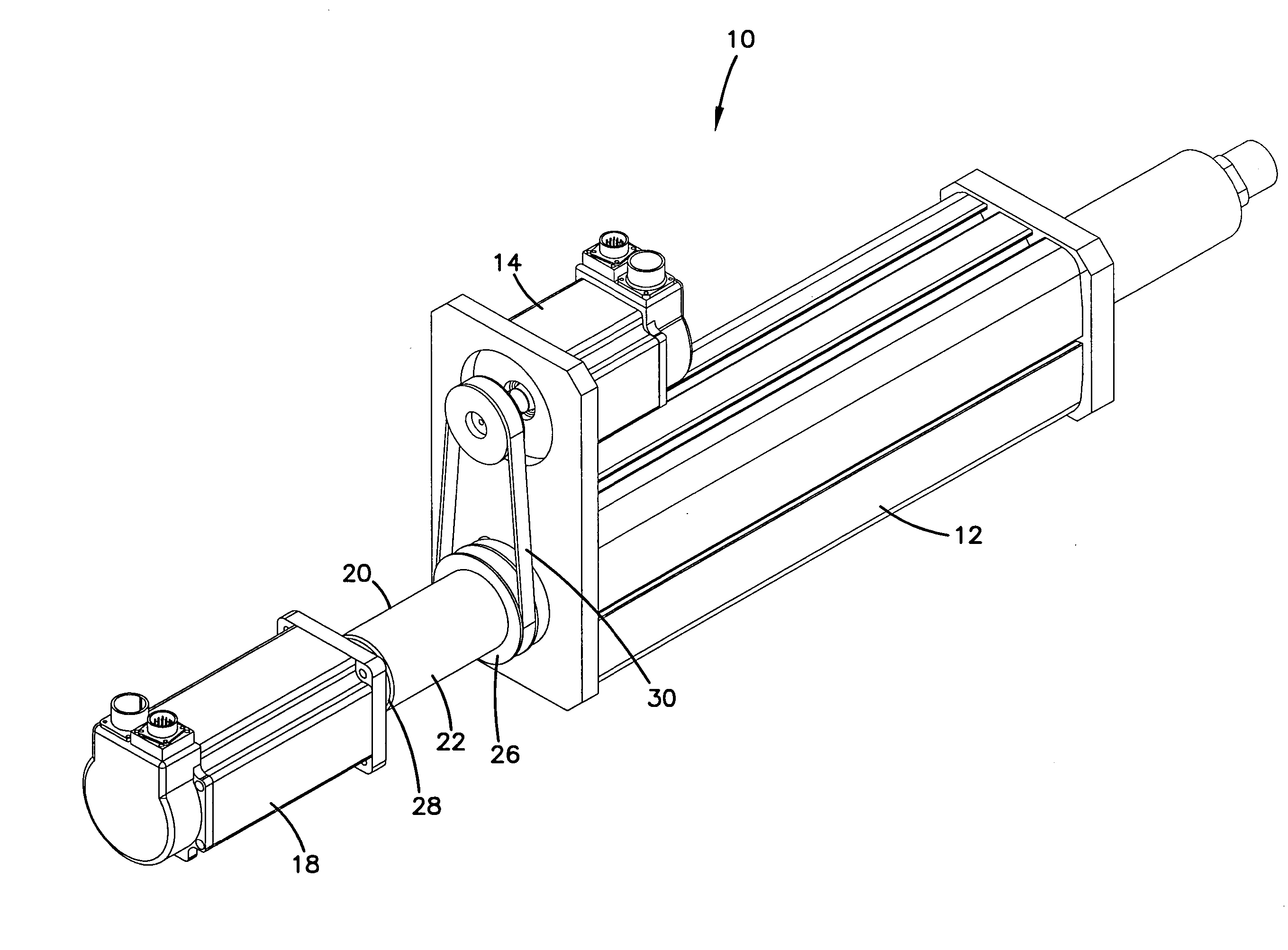
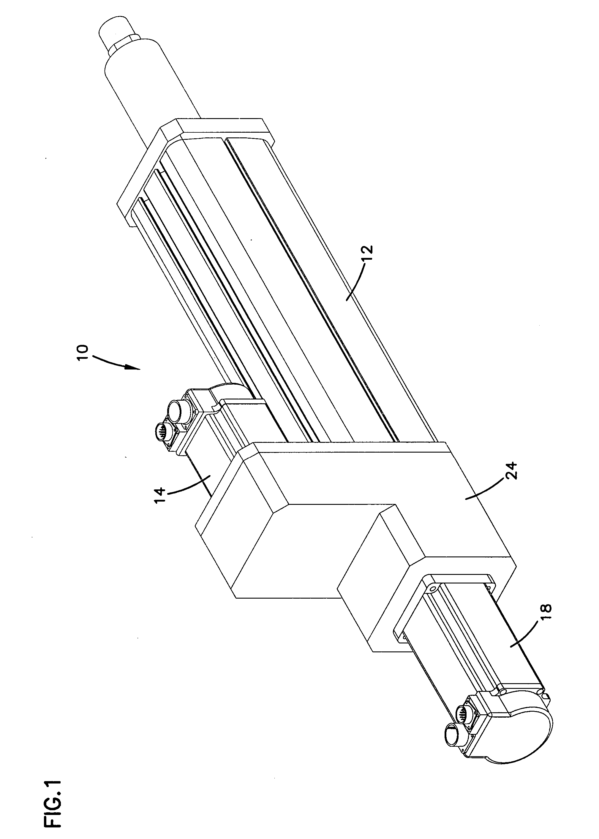
[0016]FIG. 1 is a perspective view of the linear actuator system according to the present invention;

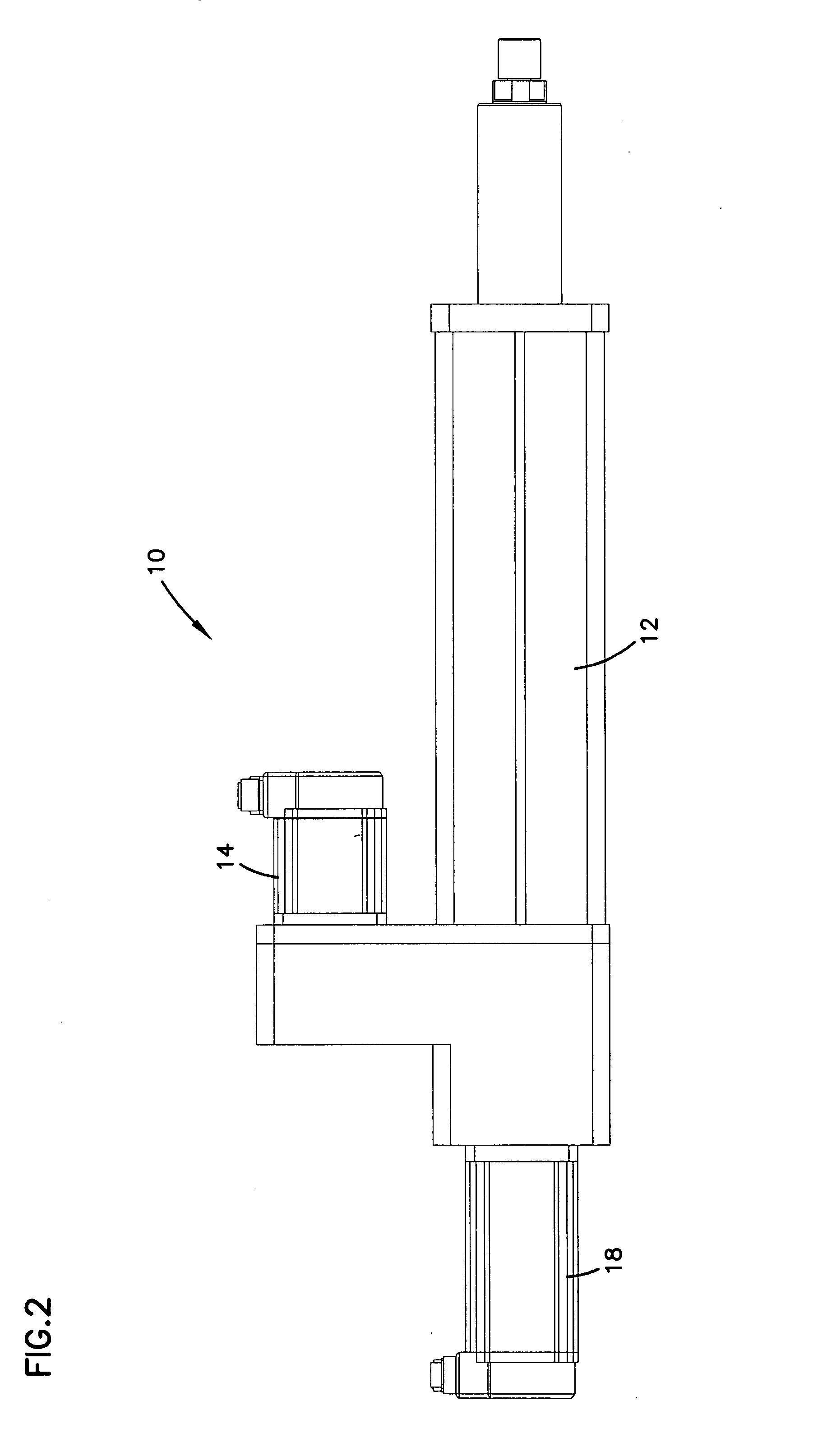
[0017]FIG. 2 is a side elevational view of the linear actuator system of FIG. 1;

[0018]FIG. 3 is top plan view of the linear actuator system of FIG. 1;

[0019]FIG. 4 is a perspective view of the linear actuator system of FIG. 1, shown with the casing of the transmission removed from the system illustrating the internal components of the transmission; and

[00...


PUM


Abstract

A linear actuator system is described that includes a linear actuator, a first motor, and a second motor. The linear actuator is configured to transmit rotational motion to linear motion. The first motor is operatively connected to the linear actuator. The second motor is also operatively connected to the linear actuator. The first motor is configured to provide a different amount of force and a different speed to the linear actuator than the second motor. Methods of operating a linear actuator are also disclosed.

Description

FIELD OF THE INVENTION [0001] The present invention relates generally to linear actuators; relates more specifically to driving a linear actuator with two motors via a transmission; and relates more specifically still to driving a rotational to linear actuator with both a high torque motor and a high speed motor using a bi-directional over-running clutch. BACKGROUND OF THE INVENTION [0002] There are many applications that require a linear actuator to both move at high speed with low force, and at low speed with high force. An example application might be a nailing machine, or a riveting or metal pressing machine. The desired machine would rapidly move the ram or rod of the linear actuator with high speed to the point where high force is needed. This first part of the cycle does not itself require high force. This first part of the cycle is typically followed by a need for a short stroke at high force (to insert a rivet or a nail for example). There are other applications that may re...

Claims


Application Information

Patent Timeline
IPC IPC(8): F16H29/22H02K41/00F16H29/20H02K41/02H02K7/06H02P1/54H02P3/00H02K7/10H02K41/06F16H27/02F16H29/02
CPCH02K7/06H02K7/108H02K16/00Y10T74/18664Y10T74/134Y10T74/18592Y10T74/18696
Inventor HOFFMANN, BENJAMINZERULL, WILLIAMWELCH, RICHARD
Owner EXLAR CORP
Features
  • Generate Ideas
  • Intellectual Property
  • Life Sciences
  • Materials
  • Tech Scout
  • Unparalleled Data Quality
  • Higher Quality Content
  • 60% Fewer Hallucinations
Learn More