
Implantable shunt or catheter enabling gradual delivery of therapeutic agents

a shunt or catheter technology, applied in the field of surgical devices, can solve the problems of increased pressure on the brain, enlargement of the ventricle, and inability to move, and achieve the effect of slow delivery of the therapeutic agent or the agen

Inactive Publication Date: 2008-02-28
WYETH LLC
View PDF6 Cites 90 Cited by
  • Summary
  • Abstract
  • Description
  • Claims
  • Application Information

AI Technical Summary

Benefits of technology

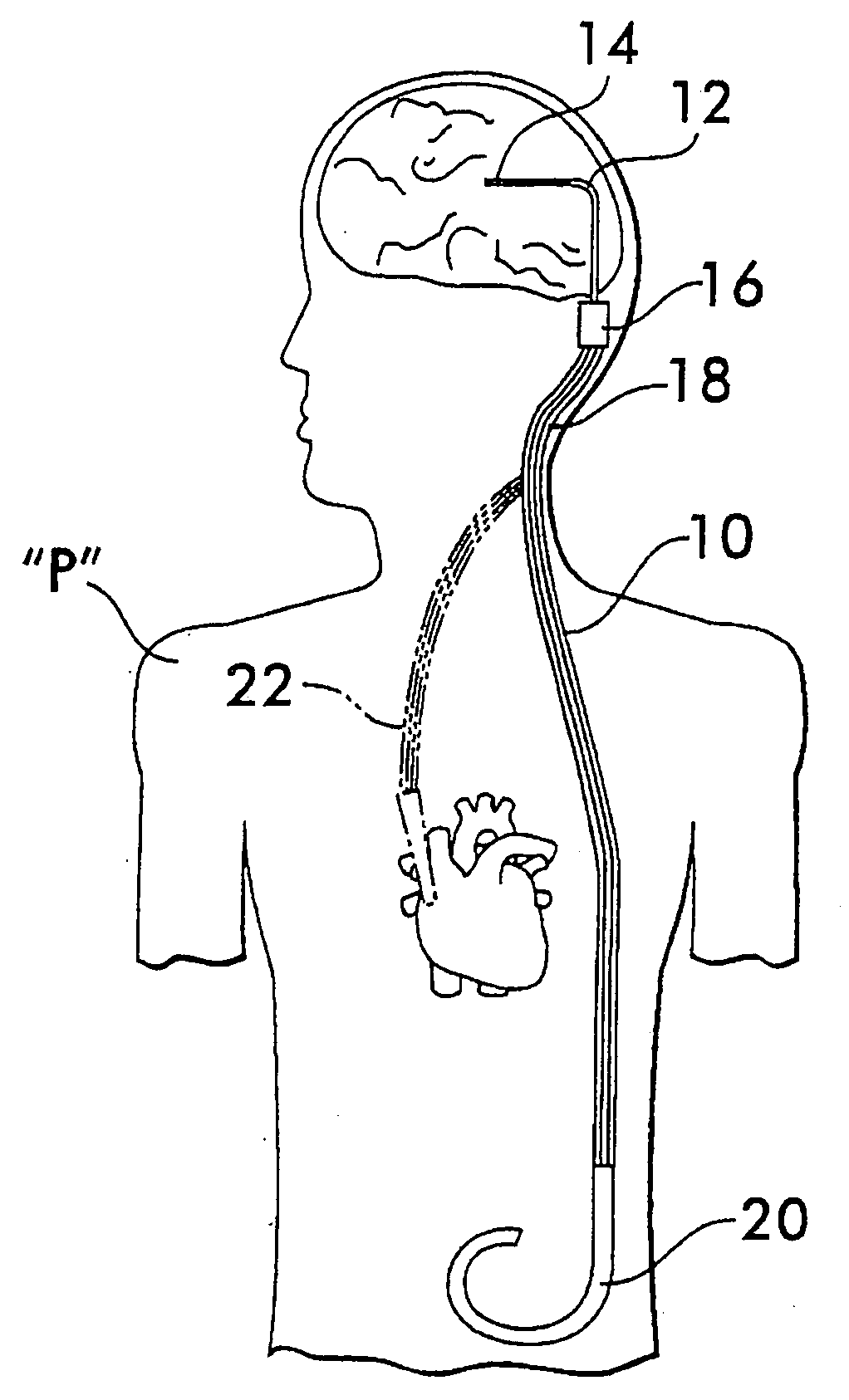
[0009]The present invention relates to an implantable catheter or shunt system for draining fluid from a body cavity. The catheter or shunt body has a wall structure that carries one or more therapeutic agents in a manner enabling slow delivery of the therapeutic agent or agents from the wall structure in situ after surgical implantation of the catheter or shunt body. As an example, release of the therapeutic agent or agents can be provided for the purposes of preventing infection, inhibiting tissue ingrowths, and / or performing some other desired medicinal function. In some contemplated embodiments of the present invention, the supply of the therapeutic agent carried by the wall structure of the implanted catheter / shunt is rechargeable and / or refillable in situ so that the gradual release of the therapeutic agent can be accomplished over an extended period of time such as the intended useful lifespan of the implanted catheter / shunt.
[0010]The invention provides an implantable shunt system for draining fluid from a body cavity, comprising a catheter and at least one therapeutic agent carried by a wall structure of said catheter, said wall structure having an outer peripheral surface and an inner peripheral surface defining a lumen through which fluid is drained from the body cavity, and said wall structure enabling gradual release of said therapeutic agent from said wall structure in situ after implantation of said catheter body.
[0011]The invention provides an implantable shunt system capable of draining fluid from a body cavity, comprising a catheter and at least one therapeutic agent carried by a wall structure of said catheter, said wall structure having an outer peripheral surface and an inner peripheral surface defining a lumen through which fluid is to be drained from the body cavity, and said wall structure capable of enabling gradual release of said therapeutic agent from said wall structure in situ after implantation of said catheter body.

Problems solved by technology

Hydrocephalus arises when normal drainage of cerebrospinal fluid is blocked creating an imbalance between the amount of the fluid being produced by the choroid plexus and the rate at which the fluid is absorbed into the bloodstream.
Such an imbalance increases pressure on the brain and causes the ventricles to enlarge.
A problem experienced with the implantation of such catheters and shunts is that the inflow end of a ventricular catheter can become obstructed or blocked due to ingrowths of choroid tissue.
This renders the system inoperative in relieving excess pressure and requires surgery to remove the system without tearing the brain tissue or causing bleeding.
Another problem is that of infection.

Method used


Image

  • Implantable shunt or catheter enabling gradual delivery of therapeutic agents
  • Implantable shunt or catheter enabling gradual delivery of therapeutic agents
  • Implantable shunt or catheter enabling gradual delivery of therapeutic agents

Examples


first embodiment

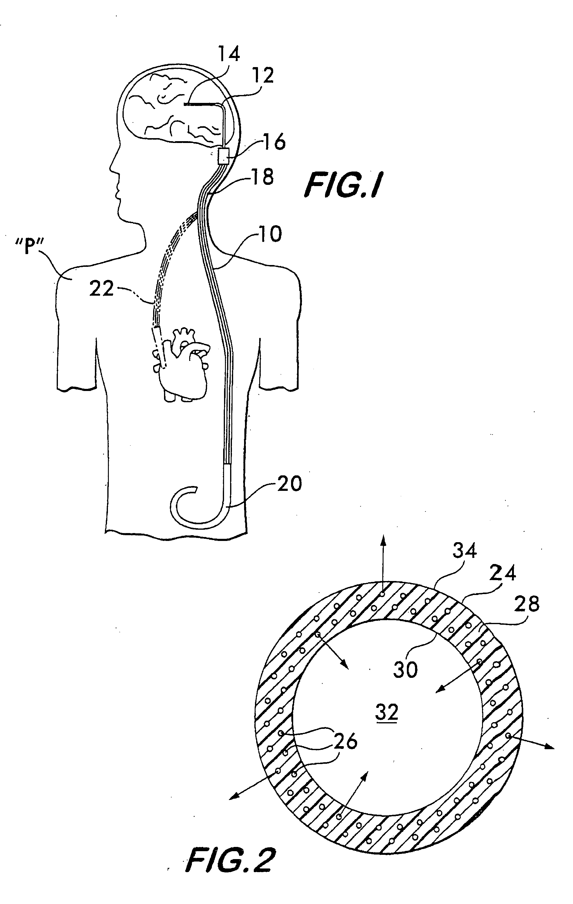
[0039]a catheter / shunt 24 according to the present invention is illustrated in cross-section in FIG. 2. The catheter / shunt 24 can be used as a ventricular catheter, a drainage shunt, or both, or can be used in other drainage or like applications. At least a predetermined length of the catheter / shunt 24 is made of a polymer, such as silicone, that contains therein a therapeutic agent 26. For example, the therapeutic agent 26 can be mixed with the polymer before manufacture of the catheter / shunt so that, upon manufacture of the catheter / shunt, the therapeutic agent 26 is distributed uniformly throughout the formed walls of the catheter / shunt. Accordingly, the wall 28 of the catheter / shunt 24 is impregnated with the therapeutic agent 26, and the therapeutic agent 26 can be slowly released therefrom in situ to deliver a controlled amount of the therapeutic agent 26 within the patient over a predetermined period of time.

[0040]By way of example, the therapeutic agent 26 can be rapamycin, ...

second embodiment

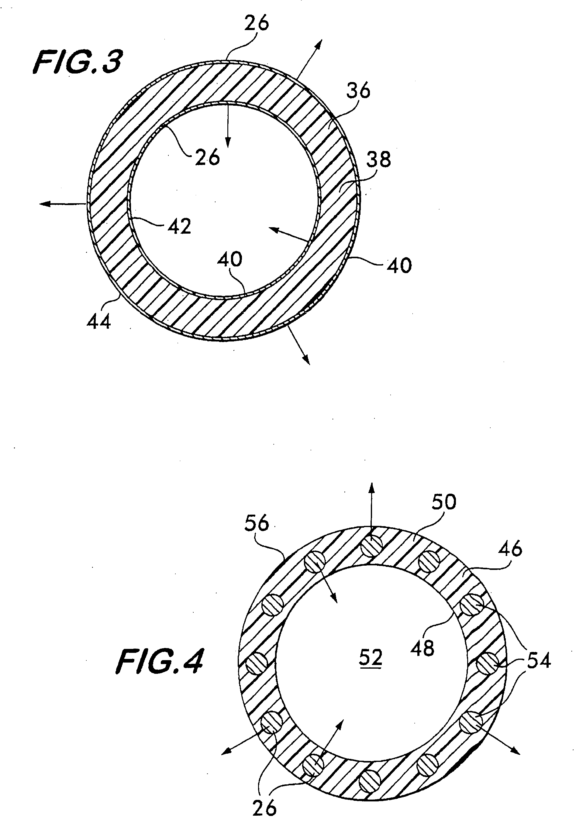
[0041]a catheter / shunt 36 according to the present invention is illustrated in cross-section in FIG. 3. The wall 38 of the catheter / shunt 36 is coated with a film or coating 40 containing a therapeutic agent 26. The film or coating 40 can be made of a solution including a mixture of the therapeutic agent 26 and a polymer carrier solution that is applied to one or both of the inner peripheral surface 42 and outer peripheral surface 44 of the wall 38 by dip-coating, spray-coating, brush-coating, spin-coating or like techniques. When the catheter / shunt 36 is implanted in a patient, the therapeutic agent 26 is gradually released therefrom over a predetermined period of time. The therapeutic agent 26 can be any of those discussed above.

[0042]A catheter / shunt 24 shown in FIG. 2 can be applied with the coating or film 40 illustrated in FIG. 3. In this case, the film 40 can be relied upon to provide an initial short-term burst / release of therapeutic agent 26 followed by a slower long-term r...


PUM

PropertyMeasurementUnit
Lengthaaaaaaaaaa
Flexibilityaaaaaaaaaa
Therapeuticaaaaaaaaaa

Abstract

An implantable catheter or shunt for draining fluid from a body cavity. The catheter or shunt body has a wall structure that carries one or more therapeutic agents in a manner enabling release of the therapeutic agent from the wall structure in situ after surgical implantation of the catheter or shunt body. The therapeutic agent can be gradually released over time to prevent infection, inhibit tissue ingrowths, and / or provide some other desired medicinal purpose. As an example, the therapeutic agent can be rapamycin or an mTOR inhibitor. According to some contemplated embodiments of the present invention, the therapeutic agent carried by the catheter / shunt is rechargeable or refillable in situ so that the therapeutic agent can be gradually released from the catheter / shunt over the expected useful life of the catheter / shunt.

Description

CROSS-REFERENCE TO RELATED APPLICATIONS[0001]This application claims the benefit under 35 USC 119(e) of U.S. Provisional Patent Application No. 60 / 840,591, filed Aug. 28, 2006.BACKGROUND OF THE INVENTION[0002]The present invention relates, in general, to surgical devices such as implantable catheters and shunts for draining fluids between different areas within the human body, and more particularly, to catheters and shunts that minimize risks of blockage and obstruction and / or infection.[0003]Shunts and catheters have been employed in surgical applications for controlling the flow of body fluids between various regions of a human body. As one example, implantable shunt systems are used in the treatment of hydrocephalus to overcome or control the lack of free circulation and / or absorption of cerebrospinal fluid within the human brain.[0004]Hydrocephalus is a neurological condition that is caused by the abnormal accumulation of cerebrospinal fluid within the ventricles, or cavities, o...

Claims


Application Information

Patent Timeline
IPC IPC(8): A61M27/00A61K31/436A61P25/00A61K9/00
CPCA61K31/436A61L29/16A61L2300/416A61L2300/406A61L31/16A61P25/00A61M27/006
Inventor DRAGOON, DEBORAH L.COHEN, JONATHAN MARC
Owner WYETH LLC
Learn More