Calibration method for air intake tracts for internal combustion engines

a technology for internal combustion engines and air intake pipes, which is applied in the direction of combustion-air/fuel-air treatment, machines/engines, instruments, etc., can solve the problems of voiding the manufacturer's warranty on the engine, performance not the priority, and damage to the engin

Active Publication Date: 2008-02-28
INJEN TECH CO LTD
View PDF2 Cites 2 Cited by
  • Summary
  • Abstract
  • Description
  • Claims
  • Application Information

AI Technical Summary

Problems solved by technology

Even if the OEM intake system is taking its air from outside the engine compartment, there still are performance-sapping design aspects to virtually all OEM intake system designs.
These pieces are designed to reduce intake sound (i.e. engine sound), and therefore performance is not the priority.
While the power improvements made available by cold air intake systems 30 are well-known, so are the problems associated with them.
In fact, some vehicle models and / or intake systems suspected to actually cause damage to the engine.
This is dangerous and further may actually void the manufacturer's warranty on the engine.
This approach, while effective, only serves to add cost and uncertainty to the intake system “upgrade.”

Method used


Image

  • Calibration method for air intake tracts for internal combustion engines
  • Calibration method for air intake tracts for internal combustion engines
  • Calibration method for air intake tracts for internal combustion engines

Examples


Embodiment Construction

[0025]The following description is provided to enable any person skilled in the art to make and use the invention and sets forth the best modes contemplated by the inventor of carrying out his invention. Various modifications, however, will remain readily apparent to those skilled in the art, since the generic principles of the present invention have been defined herein specifically to provide a Calibration Method for Air Intake Tracts for Internal Combustion Engines.

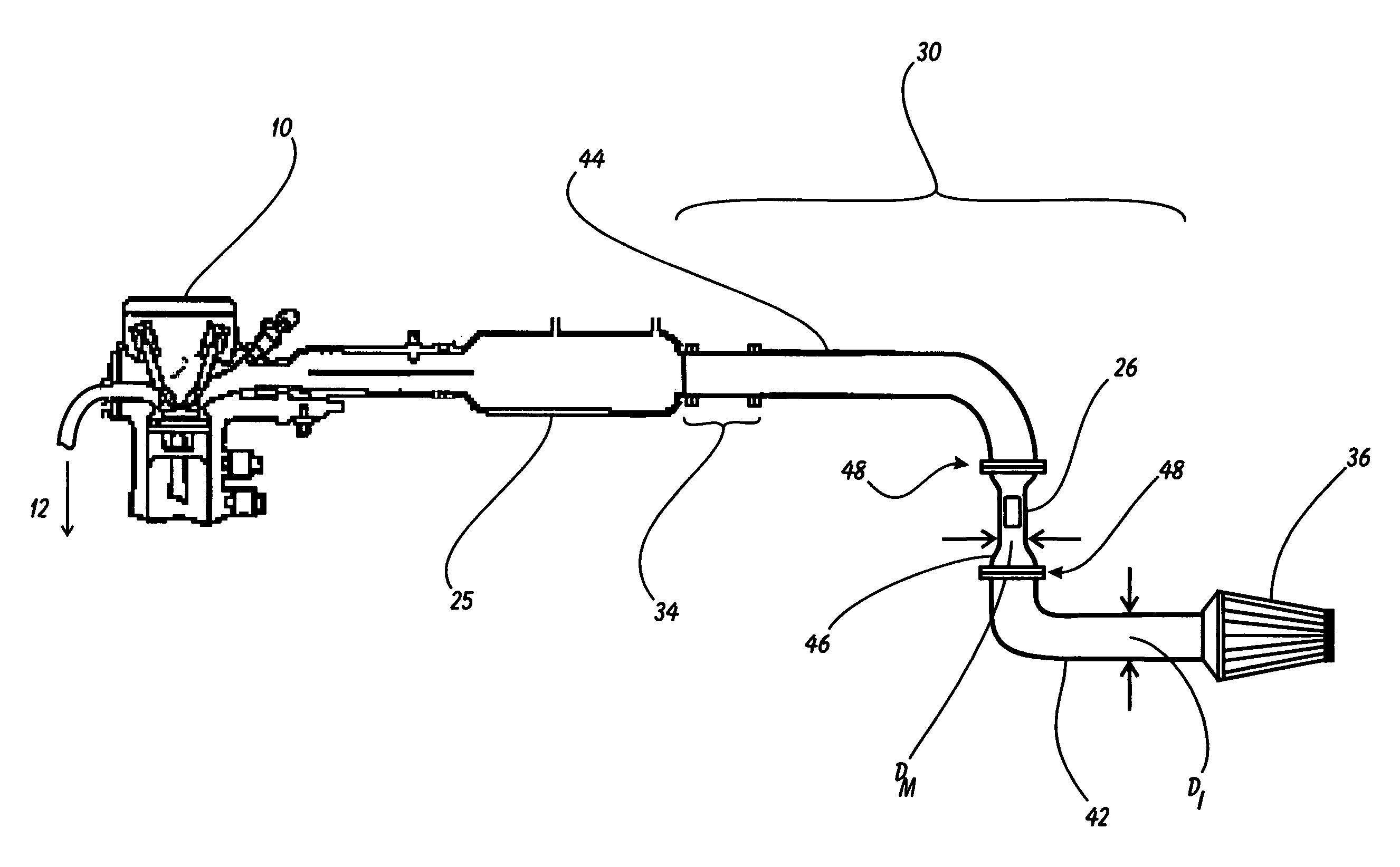
[0026]The present invention can best be understood by initial consideration of FIG. 3. FIG. 3 is a preferred embodiment of a combustion-tuning cold air intake test system 40 for use with the method of the present invention. The test system 40 is designed to provide the inventor with the necessary equipment to execute the cold air intake tuning method of the present invention, the completion of which will provide the inventor with the necessary information to produce production-quality, combustion-tuned cold air intake s...


PUM


Abstract

A Calibration Method for Air Intake Tracts for Internal Combustion Engines is disclosed. The method tunes the replacement cold air intake so that the Original Equipment Mass Airflow Sensor will function with the emissions control system without check engine light illumination. The method uses the exhaust effluent composition to benchmark the OEM intake system and then to match the cold air intake to that benchmark test result. The method could use the exhaust effluent composition for calibration as well as verification, or the method could use Sensor signal output for calibration and then exhaust effluent composition for verification of the design specification.

Description

BACKGROUND OF THE INVENTION[0001]1. Field of the Invention[0002]This invention relates generally to internal combustion engines and accessories therefor and, more specifically, to a Calibration Method for Air Intake Tracts for Internal Combustion Engines.[0003]2. Description of Related Art[0004]For the sake of this discussion, the phrase “intake system” is being used to describe the ducting and accessories that feed air to an internal combustion engine prior to the throttlebody, including the large duct, filter, and any other parts thereof. FIG. 1 is a schematic diagram of an internal combustion engine's intake tract. The mass airflow sensor 26 and emissions / central computer 28 are depicted here for reference, but will be described more fully in connection with FIG. 2 and beyond.[0005]The original equipment manufacturer (OEM) intake system 14 on a typical production vehicle consists of an air inlet 23 leading to a resonator 16, a substantial amount of plastic duct work 18, a large m...

Claims


Application Information

Patent Timeline
Patent Type & Authority Applications(United States)
IPC IPC(8): G06G7/70G01M19/00F02M51/00F01N3/00G01M99/00
CPCF02M35/04F02M35/10144F02M35/1255F02M35/1047F02M35/10386
Inventor DELGADO, RON
Owner INJEN TECH CO LTD
Why Eureka
Try Eureka