
Method and apparatus for dynamically adjusting distributed queing system and data queuing receiver reference voltages

a distributed queing system and data queuing technology, applied in the field of methods and apparatus, can solve the problems of not fitting into the ddr slot, generating a great amount of heat for processors running at higher frequencies, and limited bandwidth of sdram

Inactive Publication Date: 2008-02-28
IBM CORP
View PDF4 Cites 2 Cited by
  • Summary
  • Abstract
  • Description
  • Claims
  • Application Information

AI Technical Summary

Benefits of technology

[0015]As a result of the summarized invention, technically we have achieved a solution that provides f...

Problems solved by technology

However, SDRAM has bandwidth limitations.
However, DDR memory functions at 2.5 V, thus generating a great amount of heat for processors that run at higher frequencies.
DDR2 modules require 240-pin DIMM slots, and although they are the same length as DDR, they are keyed differently and do not fit into the DDR slot.
There are difficulties in generating the half bit time delay and in generating edge aligned DQ and DQS on DRAMs.
These difficulties lead to timing problems centering DQS (clock) in the DQ (data) window.

Method used


Image

  • Method and apparatus for dynamically adjusting distributed queing system and data queuing receiver reference voltages
  • Method and apparatus for dynamically adjusting distributed queing system and data queuing receiver reference voltages
  • Method and apparatus for dynamically adjusting distributed queing system and data queuing receiver reference voltages

Examples


Embodiment Construction

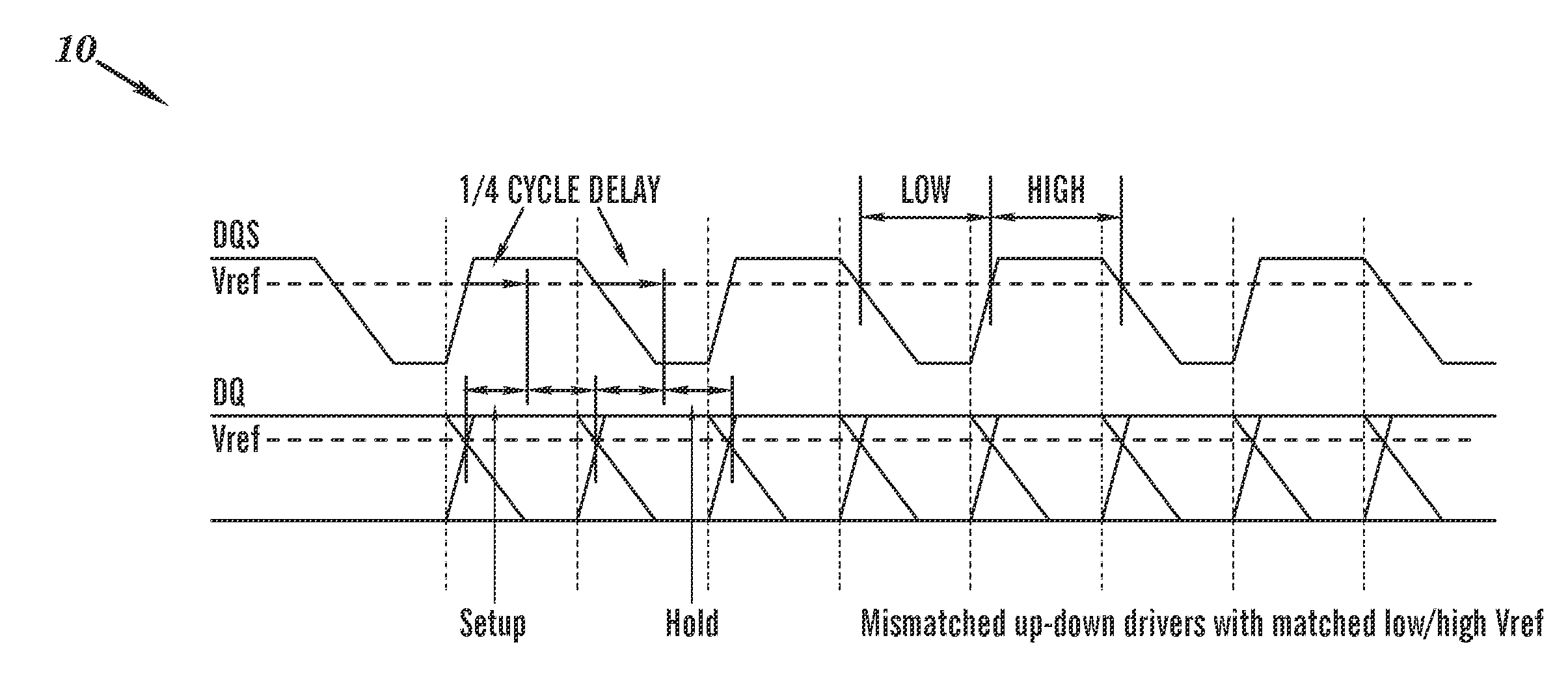
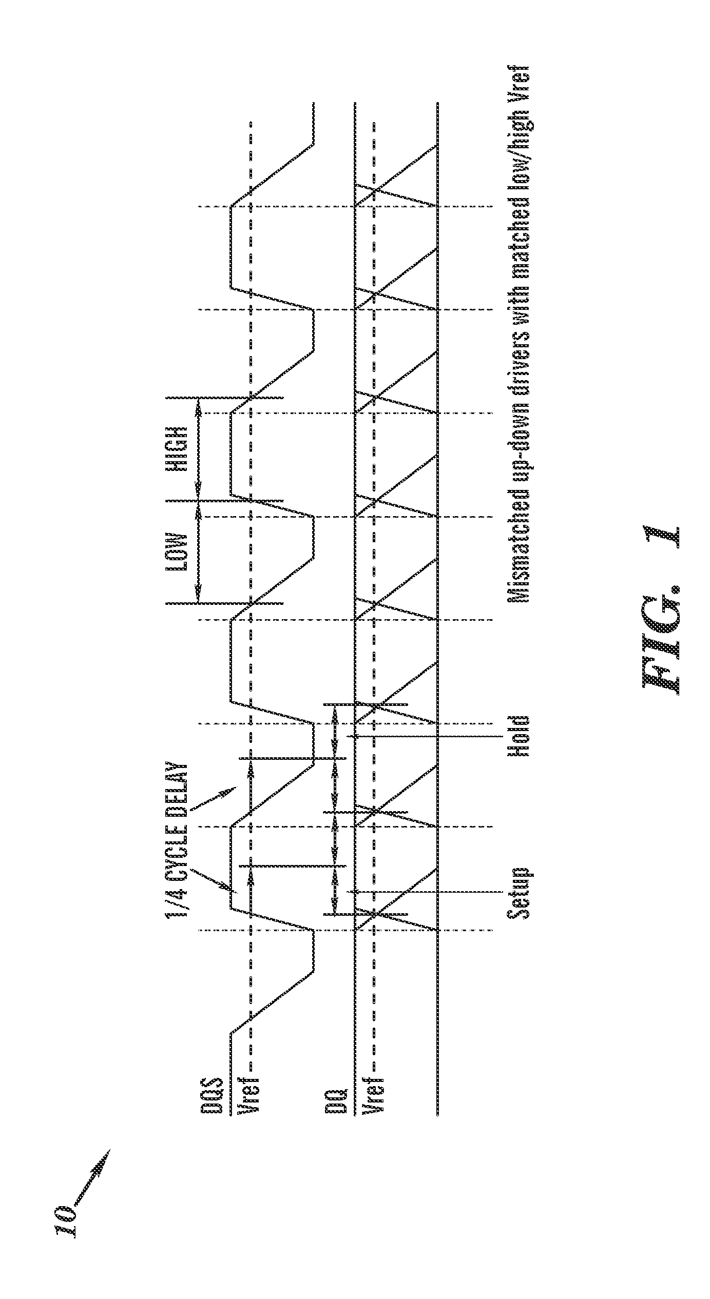
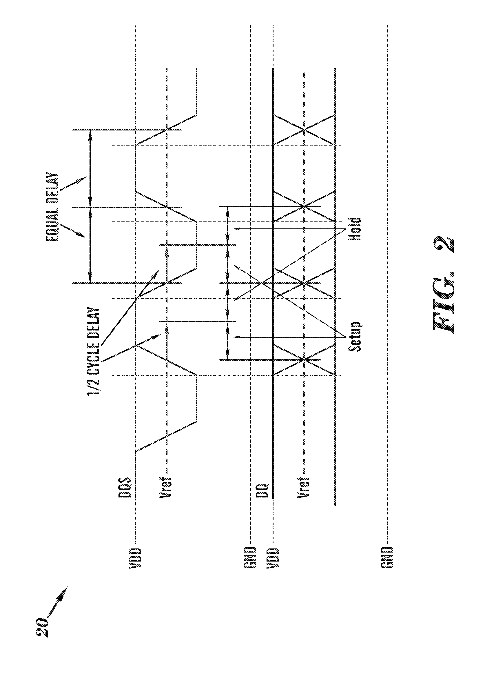
[0023]One aspect of the exemplary embodiments is a method for an efficient method for automatically setting DQS (Distributed Queuing System) and DQ (Distributed Queuing) receiver reference voltages to an optimal level. In another aspect of the exemplary embodiments a receiver sets its own reference voltage automatically to a level that gives the high and low level of DQS on a memory the same time interval, regardless of DQS rise and fall time because of the large amount of time the DQS receive signal is spent in transition.

[0024]GDDR3 (Graphics Double Data Rate, version 3) DRAM (Dynamic Random Access Memory) data (and DQS) nets are typically terminated to the voltage VDD. Most designers set their receiver reference voltages based on what they think the typical drive strength of the DRAMs is. The problem is that when DRAMs with higher impedance drivers are used, the reference voltage is set to low. Also if the DRAMs have a lower than expected driver impedance, the fixed reference vol...


PUM


Abstract

A method for automatically setting DQS (Distributed Queuing System) and DQ (Data Queuing) receiver reference voltages, the method including: using a delay string to measure a number of delay elements that match a DQS high time and a number of delay elements that match a DQS low time; wherein when the number of delay elements for the DQS low time is larger than the number of delay elements for the DQS high time, the reference voltage is decremented until the number of delay elements are equal; and wherein when the number of delay elements for the DQS low time is smaller than the number of delay elements for the DQS high time, the reference voltage is incremented until the number of delay elements are equal.

Description

TRADEMARKS[0001]IBM® is a registered trademark of International Business Machines Corporation, Armonk, N.Y., U.S.A. Other names used herein may be registered trademarks, trademarks or product names of International Business Machines Corporation or other companies.BACKGROUND OF THE INVENTION[0002]1. Field of the Invention[0003]This invention relates to computer memory, and particularly to a method for automatically setting DQS (Distributed Queuing System) and DQ (Data Queuing) receiver reference voltages to an optimal level.[0004]2. Description of Background[0005]SDRAM (Synchronous Dynamic Random Access Memory) is a type of DRAM (Dynamic Random Access Memory) memory chip that has been widely used since the latter part of the 1990s. SDRAM chips eliminate wait states because they are fast enough to be synchronized with a CPU's (Central Processing Unit) clock. The SDRAM chip is divided into two cell blocks, and data are interleaved between the cell blocks. While a bit in one block is ac...

Claims


Application Information

Patent Timeline
IPC IPC(8): G06F1/12
CPCG11C7/1051G11C7/1066H03K5/135G11C7/1093G11C2207/2254G11C7/1078
Inventor RUDRUD, PAUL
Owner IBM CORP
Learn More