Jet Mill Producing Fine Silicon Powder

Inactive Publication Date: 2008-03-06
INTEGRATED PHOTOVOLTAICS
View PDF13 Cites 40 Cited by
  • Summary
  • Abstract
  • Description
  • Claims
  • Application Information

AI Technical Summary

Benefits of technology

[0007]According to one aspect of the invention, walls of the milling chamber are formed of high purity silicon, for example, electronic grade silicon or randomly orientated polysilicon. Additionally, the pellet supply elements and powder extraction elements may be similarly formed of high purity silicon.
[0008]According to another aspect of the invention, high-purity milling gas is s

Problems solved by technology

Grinding, however, has proven insufficient for some advanced applications, particularly involving fine silicon powder of very high purity level and intended for use in different phases of the fabrication of silicon integrated circuits.
Howe

Method used


Image

  • Jet Mill Producing Fine Silicon Powder
  • Jet Mill Producing Fine Silicon Powder
  • Jet Mill Producing Fine Silicon Powder

Examples


Embodiment Construction

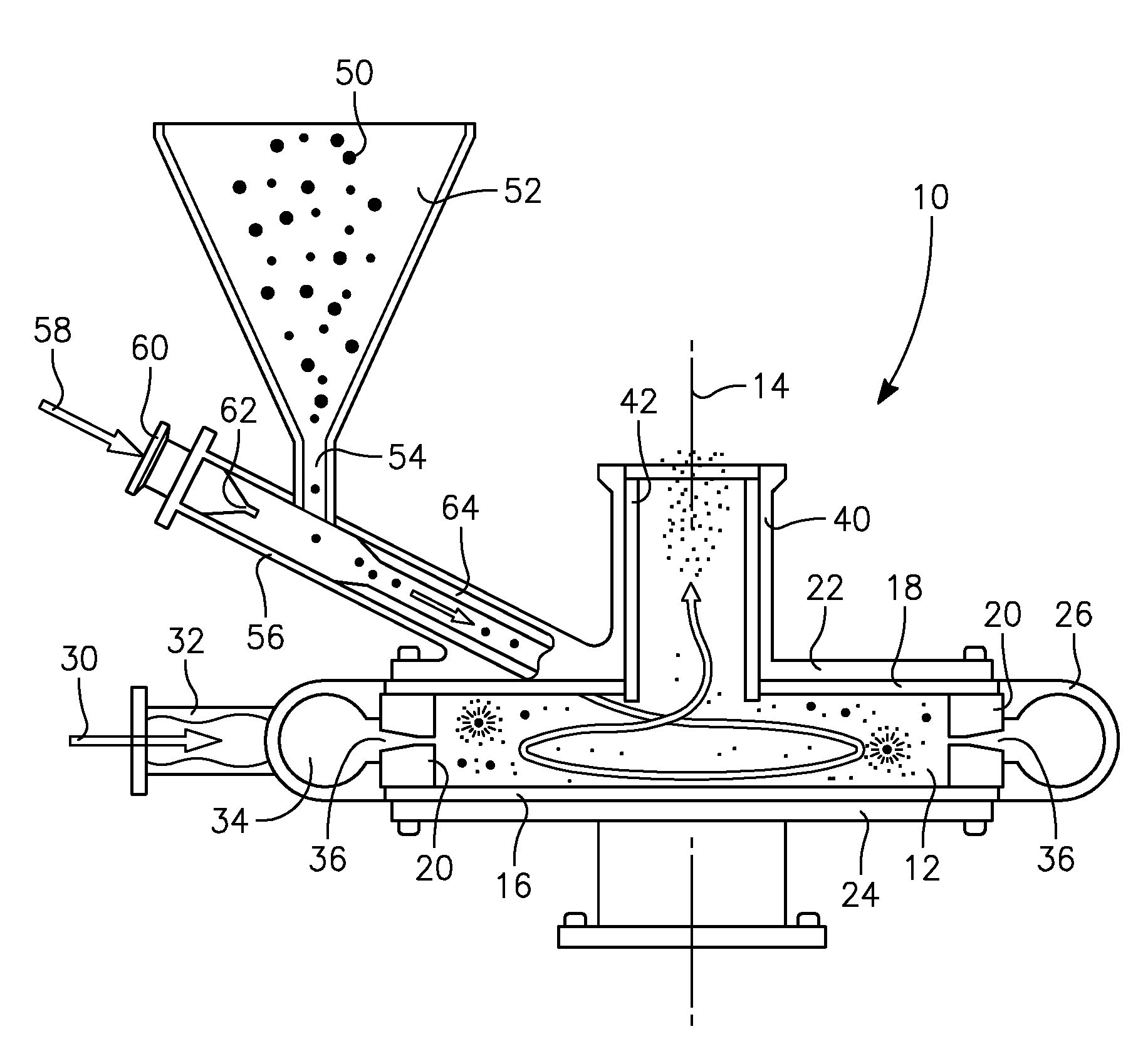
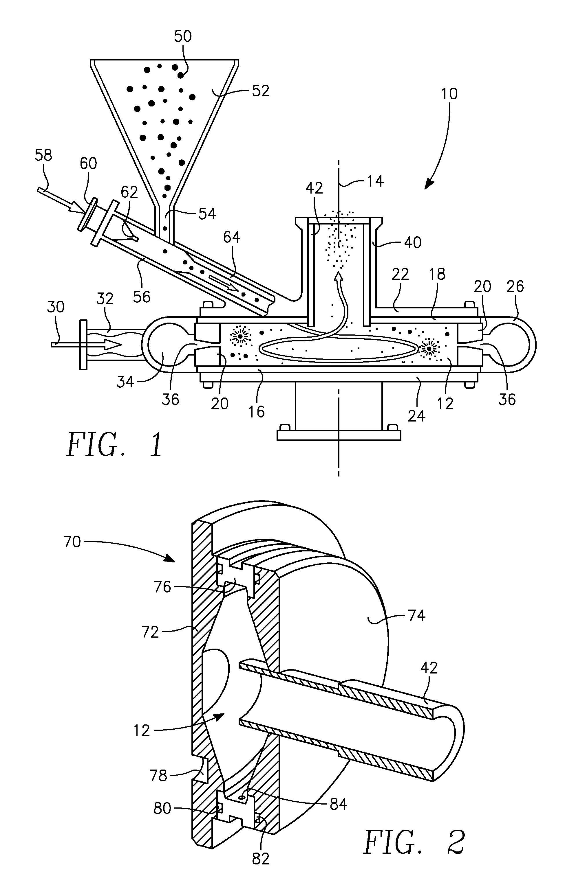
[0017]Jet milling may be used to pulverize silicon pellets into a fine silicon powder. Jet mills of differing capacities are available under the trade name Micronizer® from Sturtevant, Inc. of Hanover, Mass. The operation of such a jet mill 10 is illustrated in the partially sectioned view of FIG. 1. A generally cylindrically shaped milling chamber 12 is arranged around a chamber central axis 14 extending vertically in the illustrated embodiment and is defined by replaceable first and second axial liners 16, 18 and a replaceable circumferential liner 20 for lining the walls of the milling chamber 12. The liners 16, 18, 20 are held between first and second mill bodies 22, 24 also holding a circumferential mill body 26.

[0018]Compressed mill gas 30 is supplied through a gas intake 32 to an annular gas manifold 34 formed between the circumferential mill body 26 and the circumferential wall liner 20 and generally surrounding the milling chamber 12. A plurality, for example, six or eight ...


PUM

PropertyMeasurementUnit
Diameteraaaaaaaaaa
Flow rateaaaaaaaaaa
Levelaaaaaaaaaa

Abstract

A method of jet milling silicon powder in which silicon pellets are fed into a jet mill producing a gas vortex in which the pellets are entrained and pulverized by collisions with each other or walls of the milling chamber. The chamber walls are advantageously formed of high-purity silicon as are other parts contacting the unground pellets or ground powder. The pellets and chamber parts may be formed of electronic grade silicon but polycrystalline silicon may be used for chamber parts. Additionally, the particle feed tube in which the particles are entrained in a gas flow and the vortex finder operating as the outlet at the center of the vortex may be formed of silicon. The milling and feed gas may be nitrogen supplied from a liquid-nitrogen tank lined with stainless steel. The feed pellets may be formed by chemical vapor deposition.

Description

RELATED APPLICATION[0001]This application claims benefit of provisional application 60 / 824,681, filed Sep. 6, 2006.FIELD OF THE INVENTION[0002]The invention relates generally to grinding or pulverizing of materials. In particular, the invention relates jet milling of silicon powder and the resultant product.BACKGROUND ART[0003]Many processes require very small particles or powders of specific materials. In the past, powders could be produced by grinding and then sieving the ground particles to produce a powder of a desired size distribution. For most applications, the material of the grinding wheel can be chosen which introduces minimal contamination. Grinding, however, has proven insufficient for some advanced applications, particularly involving fine silicon powder of very high purity level and intended for use in different phases of the fabrication of silicon integrated circuits.[0004]Boyle et al. in U.S. patent application publication 2004 / 0213955 A1, describe a recently develop...

Claims


Application Information

Patent Timeline
IPC IPC(8): B02C19/06
CPCB02C19/063B02C19/061
Inventor ZEHAVI, RANAANBOYLE, JAMES E.
Owner INTEGRATED PHOTOVOLTAICS
Why Eureka
Try Eureka