Optical pickup and optical disc device

a technology of optical discs and optical pickups, applied in the field of optical disc pickups, to achieve the effect of downsizing and simplifying

Inactive Publication Date: 2008-03-06
SONY CORP
View PDF2 Cites 5 Cited by
  • Summary
  • Abstract
  • Description
  • Claims
  • Application Information

AI Technical Summary

Benefits of technology

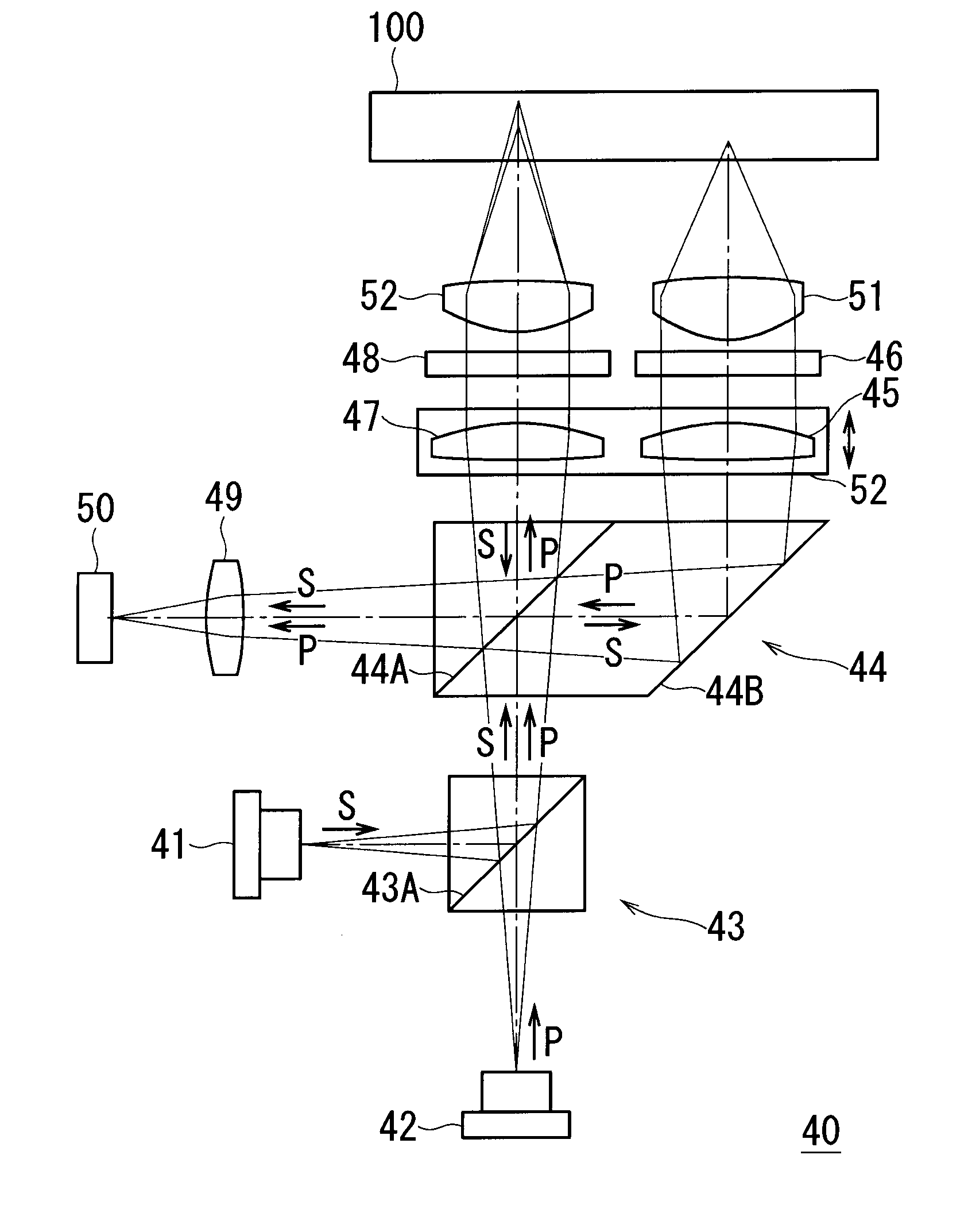
[0028]According to the present invention, there is provided an optical pickup which includes beam separation / composition means for separating the identical optical path of an incoming first optical beam and an incoming second optical beam into optical paths directed to a first objective lens and a second objective lens corresponding to the optical beams respectively, and combining optical paths of a first reflected optical beam and a second reflected optical beam which are brought about when the first optical beam and the second optical beam are reflected by an optical disc respectively so as to output the reflected optical beam along an optical path different from the optical path of the first optical beam and the second optical beam toward a light receiving element, a first collimator lens that is arranged between the beam separation / composition means and the first objective lens, and a second collimator lens that is arranged between the beam separation / composition means and the second objective lens. Accordingly, optical path separation for separating the optical path of a first and a second optical beams as approaching beams to an optical disc into optical paths directed to a first objective lens and a second objective lens corresponding to the optical beams, optical path combination for combining different optical paths of a first and a second reflected optical beams as returning beams which come in from the first and second objective lenses, and approach-and-return optical path separation for separating the optical path of the approaching beam and the optical path of the returning beam are realized by the beam separation / composition means. Furthermore, since a first and a second collimator lenses are arranged between the corresponding first and second objective lenses and the beam separation / composition means, the first and second collimator lenses can be located on the optical path of the approaching beam and the optical path of the returning beam, which makes it possible to compensate the aberration by shifting the collimator lenses in the optical axis direction. Accordingly, it becomes possible to provide an optical pickup which can be downsized and simplified and can compensate the spherical aberration, and an optical disc device using the optical pickup.

Problems solved by technology

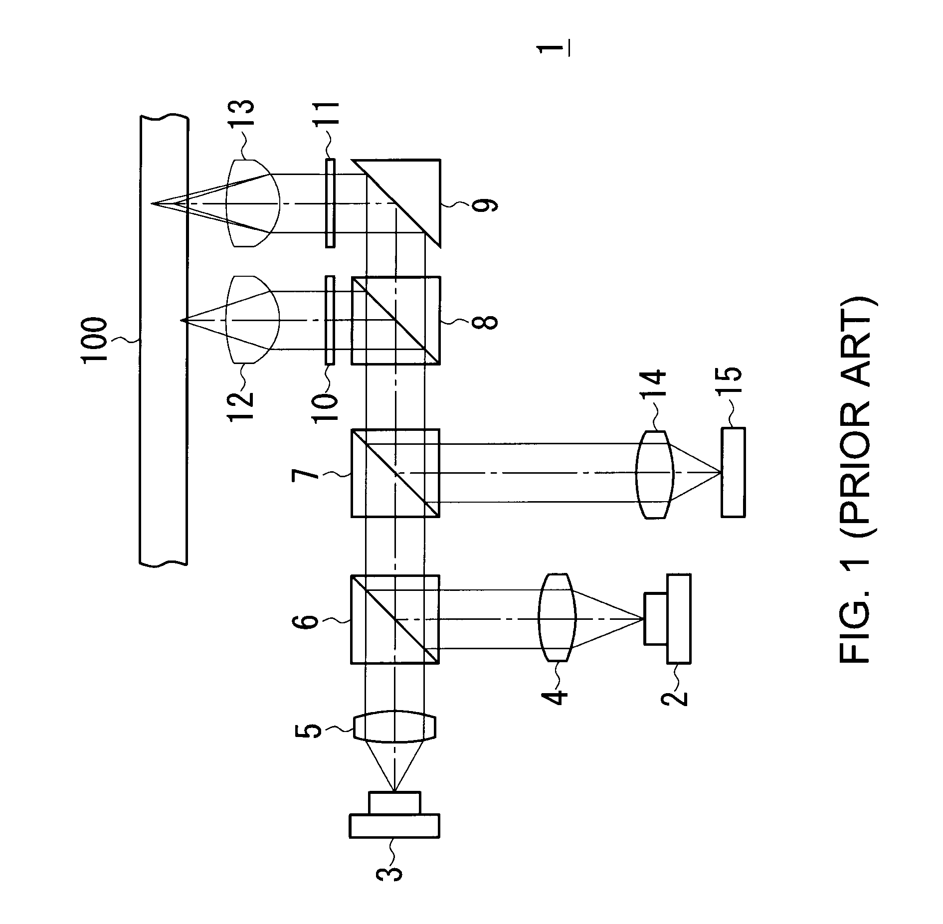
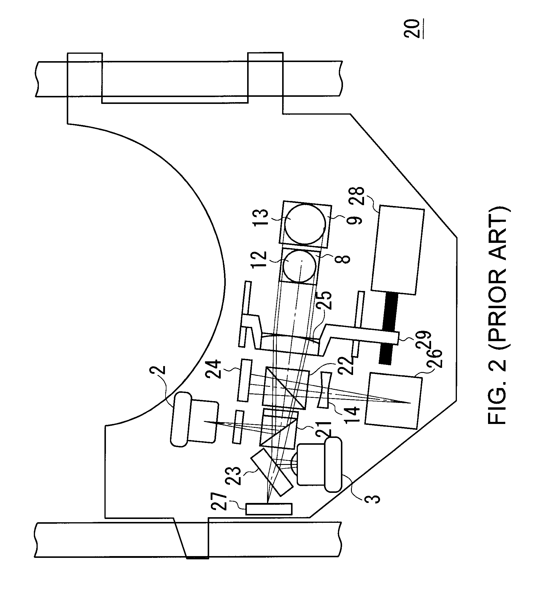
However, in the configuration of the optical pickup 1 shown in FIG. 1, since the first collimator lens 4 is arranged between the two-wavelength laser diode 2 and the first beam splitter 6 as approach-and-return optical path separation means for separating the approach-and-return optical path, when the first collimator lens 4 is shifted in the optical axis direction so as to compensate the spherical aberration, the state of condensing a reflected optical beam on the light receiving element is changed, which raises a problem that the aberration is unable to be compensated by shifting the first collimator lens 4.

Method used


Image

  • Optical pickup and optical disc device
  • Optical pickup and optical disc device
  • Optical pickup and optical disc device

Examples


Embodiment Construction

[0037]Referring to the accompanying drawings, an embodiment of the present invention will further be described below.

(1) Entire Configuration of Optical Disc Device

[0038]FIG. 3 shows a block diagram indicative of the entire configuration of an optical disc device 30, which is totally controlled by a control unit 31. The optical disc device 30 is adapted to read out information recorded on an optical disc 100 by making the control unit 31 control a drive unit 32 and a signal processing unit 33 when receiving a reproduction designation etc. from an external device, not shown, with the optical disc 100 loaded therein.

[0039]Actually, under the control of the control unit 31, the drive unit 32 makes a spindle motor 34 rotate the optical disc 100 at a desired rotational speed, and makes a thread motor 35 widely shift an optical pickup 40 in the tracking direction being the radius direction of the optical disc 100, and further makes a lens actuator 36 finely shift an objective lens in two ...


PUM


Abstract

The present invention provides an optical pickup corresponding to plural kinds of optical discs which can be downsized and simplified, and can compensate the spherical aberration. Optical path separation for separating the optical path of a first and a second optical beams as approaching beams to an optical disc 100 into optical paths directed to a first objective lens 51 and a second objective lens 52 corresponding to the optical beams, optical path combination for combining different optical paths of a first and a second reflected optical beams as returning beams which come in from the first and second objective lenses 51, 52, and approach-and-return optical path separation for separating the optical path of the approaching beam and the optical path of the returning beam are realized by the beam separation/composition prism 44. Furthermore, a first collimator lens 45 and a second collimator lens 47 are arranged between the corresponding first and second objective lenses 51, 52 and the beam separation/composition prism 44.

Description

CROSS REFERENCES TO RELATED APPLICATIONS[0001]The present invention contains subject matter related to Japanese Patent Application JP2006-233850 filed in the Japanese Patent Office on Aug. 30, 2006, the entire contents of which being incorporated herein by reference.BACKGROUND OF THE INVENTION[0002]1. Field of the Invention[0003]This invention relates to an optical pickup of an optical disc device.[0004]2. Description of the Related Art[0005]In the past, there have been widely diffused optical discs such as Compact Disc (CD) and Digital Versatile Disc (DVD) which use red laser light. On the other hand, so as to meet the demand to increase the recording density and enlarge the storage size, next-generation optical discs such as Blu-ray Disc (registered trademark) using blue laser light of 405 nm in wavelength are being diffused. Accordingly, an optical disc device that is adapted to use three kinds of discs or CD, DVD, Blu-ray Disc (also referred to as BD, hereinafter) is being devel...

Claims


Application Information

Patent Timeline
Patent Type & Authority Applications(United States)
IPC IPC(8): G02B27/10
CPCG02B27/283G11B7/1275G11B2007/0006G11B7/1376G11B7/13925G11B7/1356
Inventor ARAI, MASAKI
Owner SONY CORP
Why Eureka
Try Eureka