Multiple bit rate optical communication method, optical network unit and optical line terminal

a optical network technology, applied in the field of multi-bit rate optical communication methods, optical network units and optical line terminals, can solve the problems of incompatibility with existing systems, burden of costs, and complex device upgrades, so as to reduce the upgrade cost of optical network units and manpower, and ensure compatibility with existing systems. , the effect of ensuring compatibility

Inactive Publication Date: 2008-03-06
FUJITSU LTD
View PDF3 Cites 35 Cited by
  • Summary
  • Abstract
  • Description
  • Claims
  • Application Information

AI Technical Summary

Benefits of technology

[0035]According to the present invention, as described above, even when optical network units for which a single bit rate A1 is first set are accommodated and an optical network unit for which a bit rate A2 that is not related to the bit rate A1 as a multiple of a natural number and is different from the bit rate A1 is additionally accommodated, or existing optical network units are adapted to receive at the bit rate A2, particularly a signal transmit timing from optical network units in an upstream transmission d

Problems solved by technology

HEI 8-8954 is incompatible with existing systems, because existing systems such as a gigabit-capable passive optical network (G-PON) standardized by ITU (International Telecommunication Union) do not adopt a transmission method in which the bit rate is changed for each service in a physical layer.
Moreover, since the technology described in the above

Method used


Image

  • Multiple bit rate optical communication method, optical network unit and optical line terminal
  • Multiple bit rate optical communication method, optical network unit and optical line terminal
  • Multiple bit rate optical communication method, optical network unit and optical line terminal

Examples


first embodiment

[A] Description of the First Embodiment

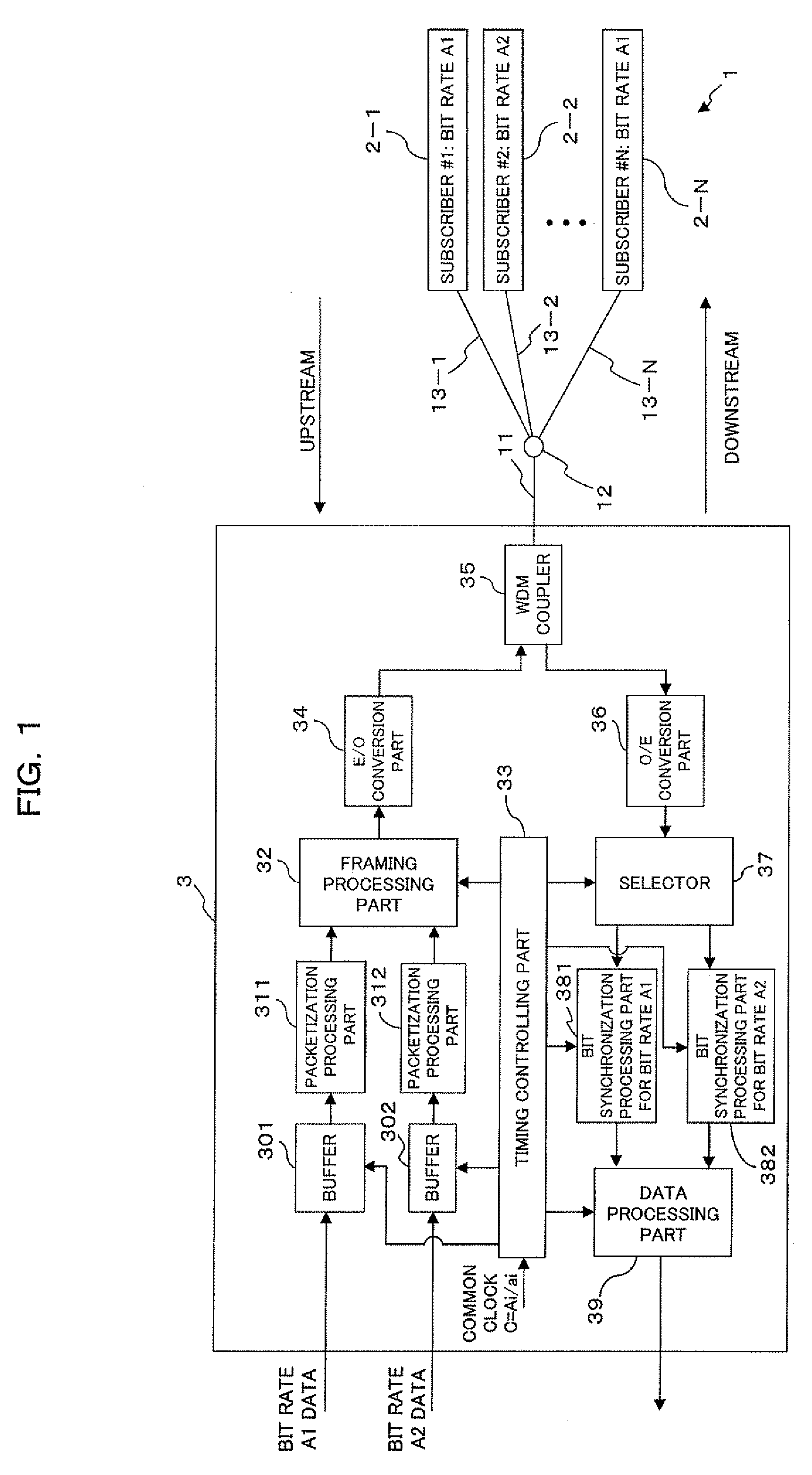
[0049]FIG. 1 is a block diagram showing the configuration of principal parts of a PON system (multiple bit rate optical communication system) according to an embodiment of the present invention. A PON system 1 shown in FIG. 1 is comprised of an optical line terminal (hereinafter referred to as an OLT) 3, N (N is an integer equal to or greater than 2) optical network units (hereinafter referred to as an ONU) 2-1 to 2-N (denoted simply as an ONU 2 if not to be distinguished) corresponding to N subscribers #1 to #N, a branching / multiplexing coupler 12, an optical fiber 11 connecting the OLT 3 and the branching / multiplexing coupler 12, optical fibers 13-1 to 13-N (denoted simply as an optical fiber 13 if not to be distinguished) connecting the branching / multiplexing coupler 12 and each ONU 2-1 to 2-N.

[0050]Here, at least one communication bit rate of a plurality (k) of communication bit rates Ai (i=1, . . . , k; k is an integer equal to or greater ...

second embodiment

[B] Description of the Second Embodiment

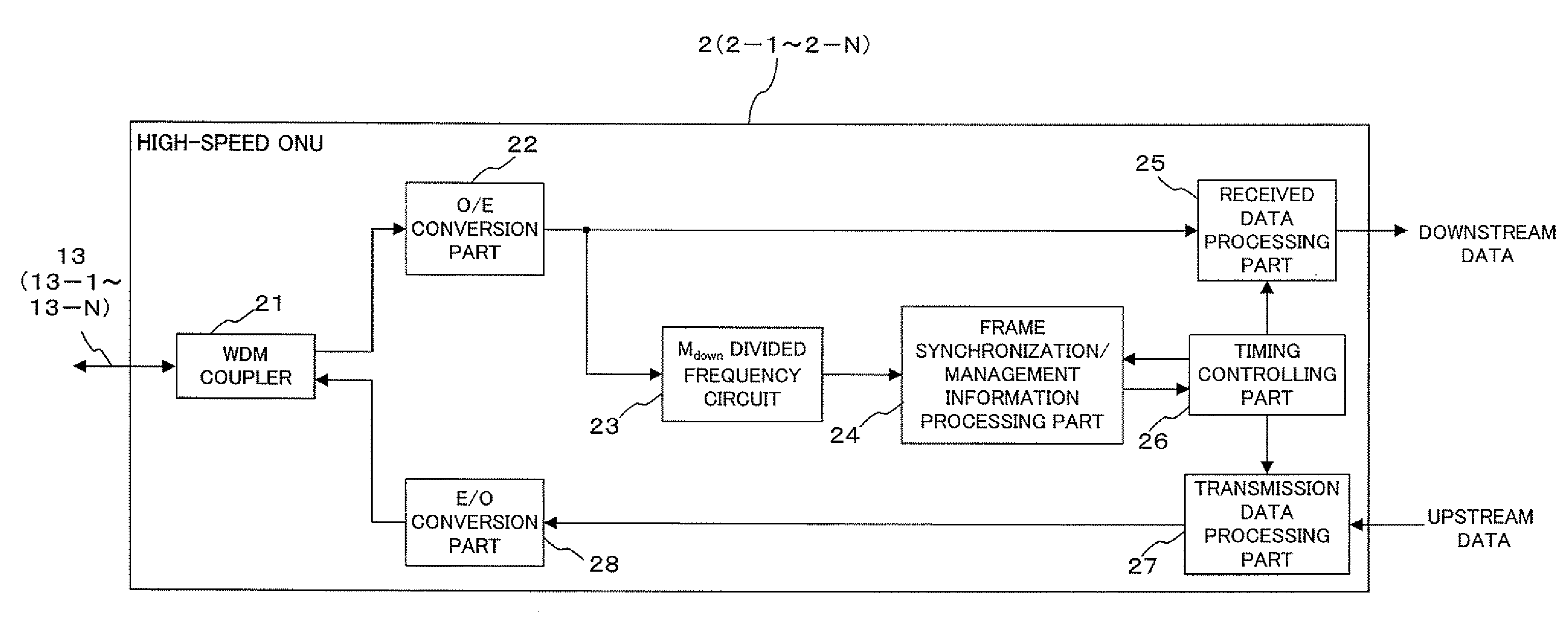
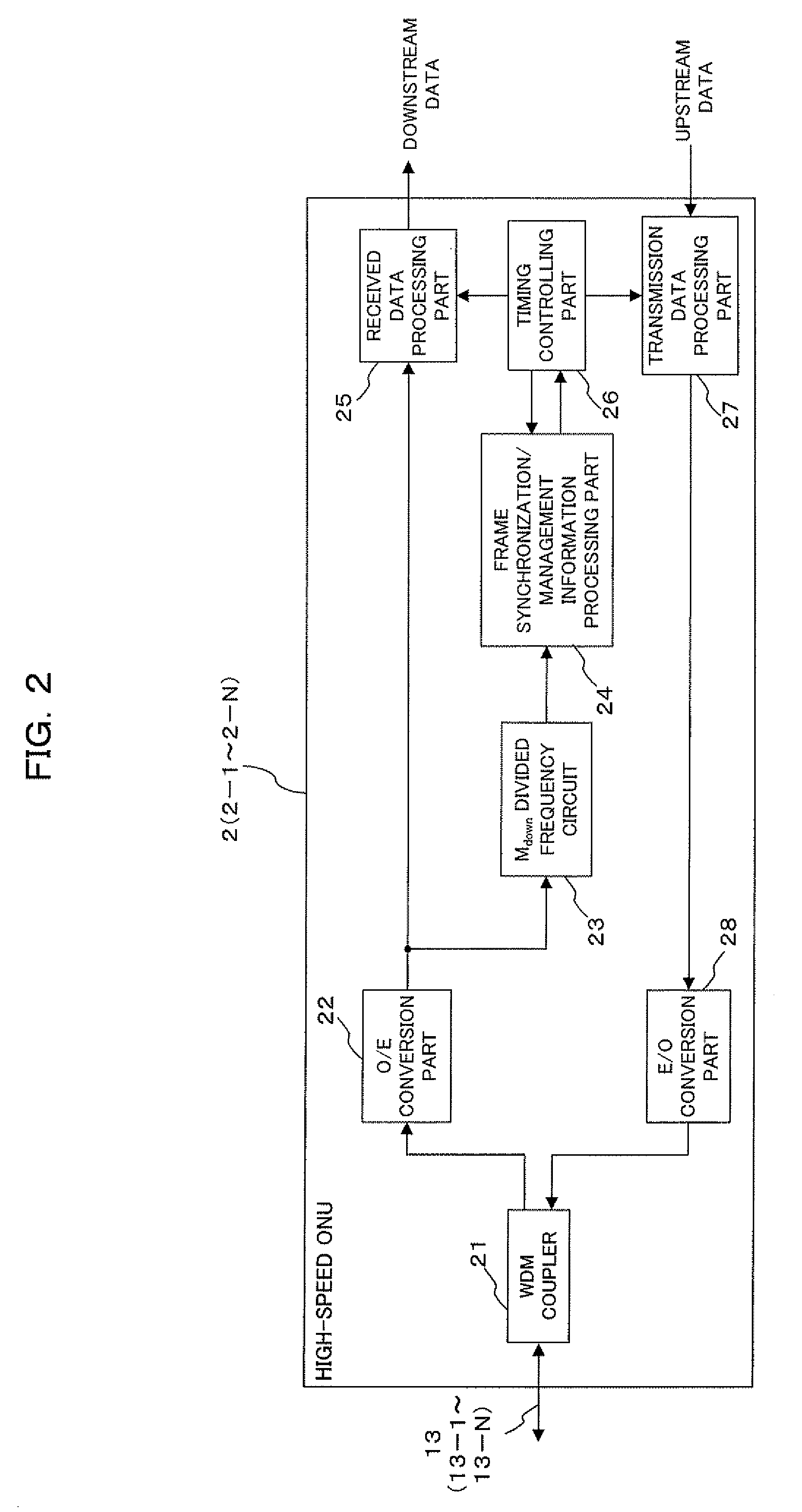
[0114]FIG. 7 is a block diagram showing the configuration of principal parts of a PON system (multiple bit rate optical communication system) according to the second embodiment of the present invention. Like the PON system 1 in the first embodiment described above, a PON system 1A shown in FIG. 7 is comprised of an OLT 3A, ONU 2A-1 to 2A-N (denoted simply as an ONU 2A if not to be distinguished), the branching / multiplexing coupler 12, and the optical fibers 11 and 13.

[0115]Here, in the PON system 1A according to the second embodiment, if k [k is an integer equal to or greater than 2; k=2 in the present embodiment] different communication bit rates Ai [i=1, . . . , k], which are not related to each other as multiples of natural numbers, set for the ONU 2A exist, transmission through the optical fibers 11 and 13 and the branching / multiplexing coupler 12 is performed by performing a rate conversion of signals handled by the ONU 2A to which at lea...


PUM


Abstract

The present invention is a method of transmitting data of different bit rates in a simple manner and, if positive minimal multiples whose multiple operation values on the bit time lengths 1/Ai for a plurality of communication bit rates Ai become common are minimal multiples ai respectively, an optical line terminal constitutes a time division multiplex signal composed of a first data area having a bit rate Ai/ai and including frame synchronization information and a second data area in which packets addressed to each optical network unit of the bit rate Ai are time division multiplexed, and transmits the time division multiplex signal to a plurality of optical network units via a branching/multiplexing means.

Description

BACKGROUND OF THE INVENTION[0001]1) Field of the Invention[0002]The present invention relates to a multiple bit rate optical communication method, an optical network unit and an optical line terminal, and relates, for example, to a technique suitable for use in a system in which a passive optical network (PON) is adopted.[0003]2) Description of the Related Art[0004]At present, as a subscriber optical fiber network system intended for subscriber homes such as ordinary households, for example, a system connecting an optical line terminal provided in a regional office set up in a central office or the like and optical network units set up in a plurality of subscriber homes using optical fibers is known. Among others, a configuration in which one optical fiber performing input / output of optical data signals from a regional office is branched off in a plurality of destinations by a power splitter, which is a passive element, and an optical network unit of each subscriber home is connecte...

Claims


Application Information

Patent Timeline
IPC IPC(8): H04J14/08H04B10/272H04B10/556H04J3/00
CPCH04J3/1617H04J3/22H04J3/1694H04B10/00H04B10/25H04B10/2581H04J14/08
Inventor MORI, KAZUYUKI
Owner FUJITSU LTD
Why Eureka
Try Eureka