Boiler and combustion control method

a combustion control and boiler technology, applied in the direction of combustion regulation, mechanical equipment, lighting and heating apparatus, etc., can solve the problems of not being able to accurately control the air ratio, requiring complicated construction and control, and not being able to propose a boiler or a combustion control method capable of controlling both the air and the combustion ratio, etc., to achieve suppress the generation of nox in the exhaust gas, simple construction, and stable manner

Inactive Publication Date: 2008-03-06
MIURA COMPANY LIMITED
View PDF8 Cites 12 Cited by
  • Summary
  • Abstract
  • Description
  • Claims
  • Application Information

AI Technical Summary

Benefits of technology

[0014]The boiler according to the present invention has a relatively simple construction, and is capable of performing combustion at a predetermined air ratio, suppressing generation of NOx in the exhaust gas in a stable manner, and performing stable combustion with high thermal efficiency. Further, according to the combustion control method of the present invention, it is possible to suppress generation of NOx to a level of 12 ppm or less in normal combustion.

Problems solved by technology

However, none of the above-mentioned conventional techniques proposes a boiler or a combustion control method capable of controlling both the air ratio and the NOx generation in the exhaust gas and suppressing generation of NOx in a stable manner even if there is a change in outside temperature due to seasonal variations or the like.
However, it is intended for the control of the air ratio when the air ratio is outside a predetermined range, but it is not capable of accurately controlling the air ratio.
The air ratio automatic correction system for a combustion apparatus proposed in JP 10-47654 A has a problem in that it requires a complicated construction and control.

Method used


Image

  • Boiler and combustion control method
  • Boiler and combustion control method
  • Boiler and combustion control method

Examples


Embodiment Construction

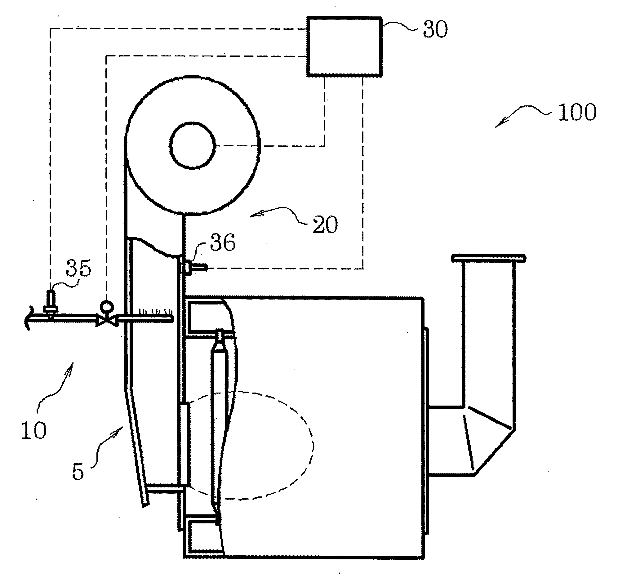
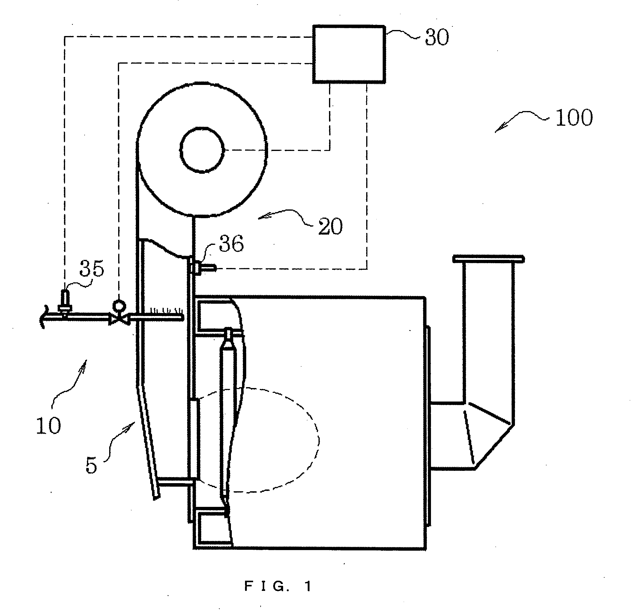
[0024]In the following, a boiler according to an embodiment of the present invention will be described with reference to the drawings. The boiler according to the present invention is provided with a control device for adjusting air quantity based on temperature changes of air and fuel. FIG. 1 is a schematic view of an embodiment thereof. As shown in FIG. 1, a boiler 100 has a burner 5, a fuel supply device 10 for supplying fuel to the burner 5, a blowing device 20 for supplying air to the burner 5, and a control device 30 for controlling the amount of fuel supplied to the burner 5 and the quantity of air supplied to the burner 5; further, the boiler 100 has a fuel temperature measuring device 35 for measuring the temperature of the fuel supplied to the burner 5 and transmitting a corresponding signal to the control device 30, and an air temperature measuring device 36 for measuring the temperature of the air supplied to the burner 5 and transmitting a corresponding signal to the co...


PUM


Abstract

Provided is a boiler (100) including: a burner (5); a fuel supply unit (10) for supplying fuel to the burner (5); a blowing unit (20) for supplying air to the burner (5); and a control unit (30) for adjusting an amount of fuel to be supplied to the burner (5) and a quantity of air to be supplied to the burner (5), in which the control unit (30) has a reference amount computing portion for calculating a reference fuel amount and a reference air quantity to be supplied to the burner (5) with respect to a required load, an air quantity computing portion that corrects the reference air quantity based on a temperature of the air to be supplied to the burner (5) and a temperature of the fuel to be supplied to the burner (5) and calculates the corrected air quantity as a supply air quantity, and a control portion that controls combustion at the burner based on the reference fuel amount and the supply air quantity.

Description

BACKGROUND OF THE INVENTION[0001]1. Field of the Invention[0002]The present invention relates to a boiler and a combustion control method making it possible to perform combustion at a predetermined air ratio and to suppress generation of NOx in the exhaust gas.[0003]2. Description of the Related Art[0004]It is important for a boiler to be capable of performing stable combustion with high thermal efficiency. In view of this, there have been proposed air ratio control boilers or combustion apparatuses in which control is performed such that combustion is performed at a predetermined air ratio.[0005]For example, JP 2001-272030 A proposes an air-fuel ratio control (air ratio control) monitoring method for a burner in a boiler and an air-fuel ratio control monitoring apparatus for executing the method. In the method and the apparatus, in response to a load command from a control panel, the pressure of the combustion air to be supplied to the burner and the pressure of the fuel to be supp...

Claims


Application Information

Patent Timeline
Patent Type & Authority Applications(United States)
IPC IPC(8): F23N1/02
CPCF23K2401/201F23K2900/05001F23N2041/04F23N2025/20F23N2033/08F23N3/002F23N2225/20F23N2233/08F23N2241/04F23K2400/201F23N5/02F23N1/00F23N1/04
Inventor FUJIWARA, TATSUYA
Owner MIURA COMPANY LIMITED
Why Eureka
Try Eureka