Method and apparatus for pressure reducing valve to reduce fuel pressure in a common rail

a technology of pressure reducing valve and fuel pressure, which is applied in the direction of electric control, speed sensing governor, instruments, etc., can solve the problems of fuel accumulating device breaking, pressure on the fuel accumulating device over fuel pressure on the fuel accumulating device undershooting the target value, etc., to prevent fuel pressure from rising, stop discharging high-pressure fuel, and close the pressure reducing valve

Inactive Publication Date: 2008-03-06
DENSO CORP
View PDF14 Cites 47 Cited by
  • Summary
  • Abstract
  • Description
  • Claims
  • Application Information

AI Technical Summary

Benefits of technology

[0051]Thus, with the execution of the second computer program, the ECU controls output a command signal for closing the pressure reducing valve before the target pressure meeting time. Therefore, it is possible to reliab

Problems solved by technology

Thus, if a target value of fuel pressure in the fuel accumulating device is set near the upper limit value over which the fuel accumulation cannot withstand, an actual pressure on the fuel accumulating device may overshoot the target value during the increase of the fuel pressure in the fuel accumulating device.
Hence, in the worst case, the fuel accumulating device will be broken since fuel pressure therein exceeds the limit value.
Further, if a target value of the fuel pressure in the fuel accumulating devic

Method used


Image

  • Method and apparatus for pressure reducing valve to reduce fuel pressure in a common rail
  • Method and apparatus for pressure reducing valve to reduce fuel pressure in a common rail
  • Method and apparatus for pressure reducing valve to reduce fuel pressure in a common rail

Examples


Embodiment Construction

[0117]In order to describe the present invention in more detail, the various embodiments of the present invention will now be described hereafter with references to accompanying drawings.

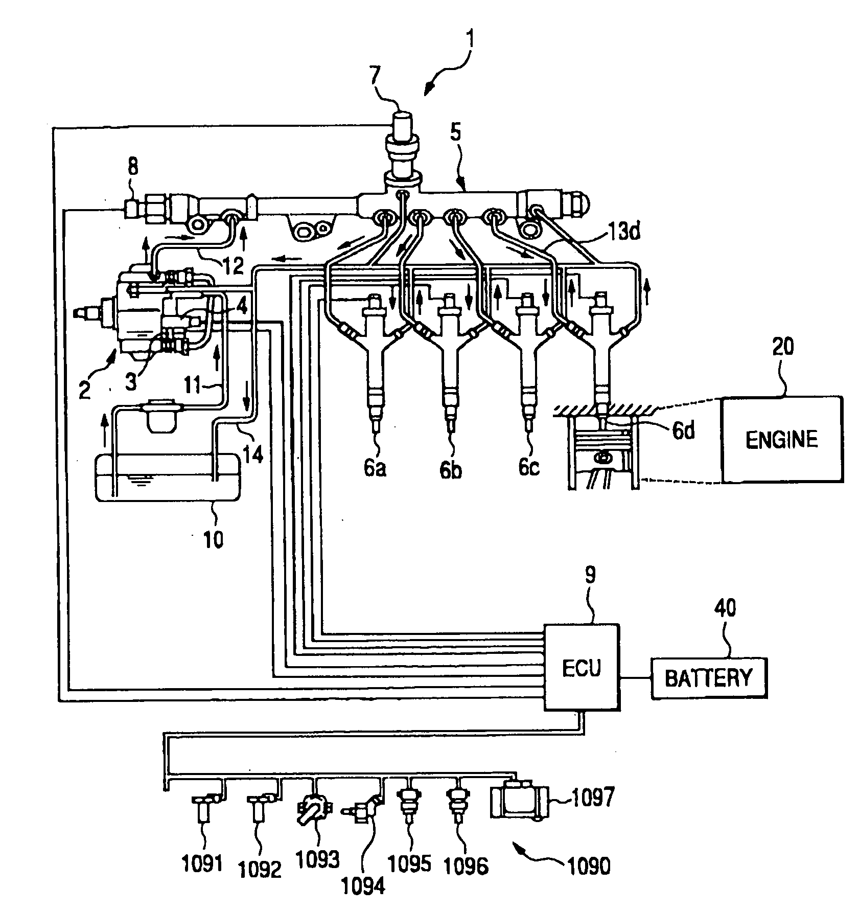
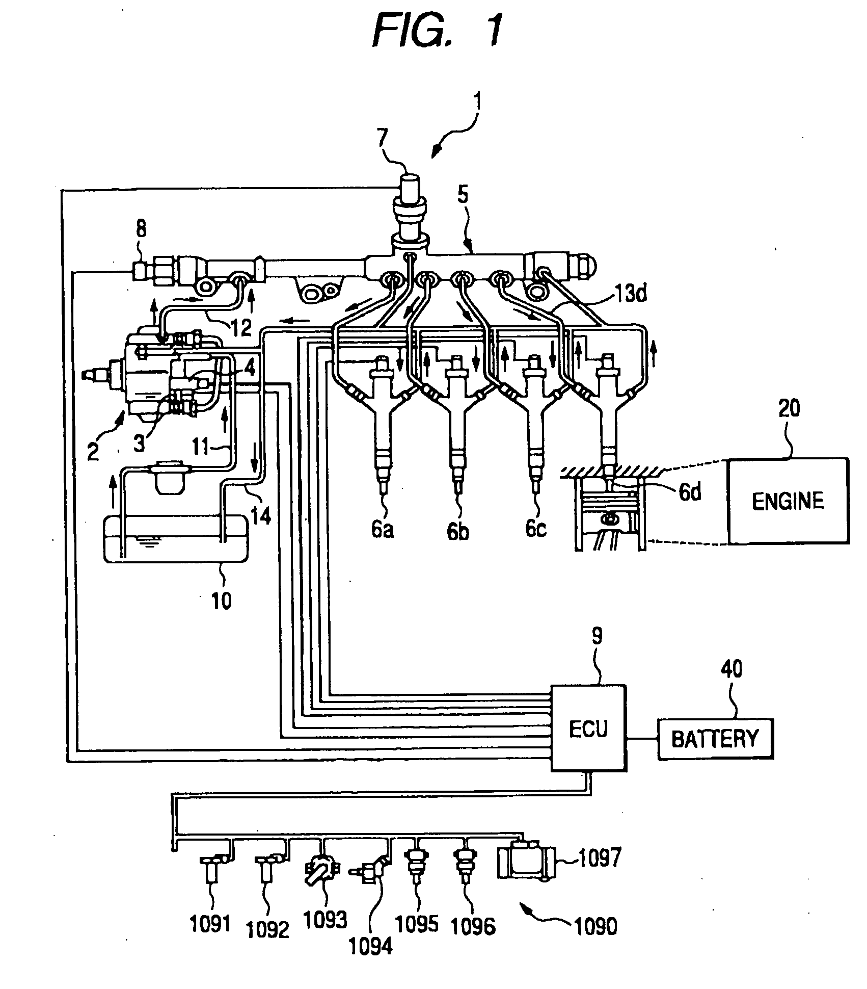
[0118]FIG. 1 is a schematic description of a common rail type fuel injection system i according to the present invention.

[0119]As shown in FIG. 1, there is the common rail type fuel injection system 1, which is, for example, a system for injecting fuel to an internal combustion engine 20 such as a four cylinder diesel engine. The common rail type fuel injection system 1 includes a high pressure pump 2 on which a fuel temperature sensor 3 is mounted, a suction control valve 4, a common rail 5, injectors 6 (6a, 6n, 6c, and 6d in FIG. 1), a pressure reducing valve 7, a fuel pressure sensor 8, and an engine control unit (ECU) 9.

[0120]The common rail 5 accumulates fuel which is highly pressurized by the high pressure pump 2 so as to be at a high pressure corresponding to a fuel injection pressure, at whi...


PUM


Abstract

It is a objective of the present invention to provide a control apparatus which is capable of compensating a delay time for opening a pressure reducing valve since an electronic control unit sends a command signal for driving the pressure reducing valve so as to discharge high pressure fuel in a fuel accumulating device of a fuel injection system for the internal combustion engine. The delay time control apparatus for opening a pressure reducing valve has a potential for avoiding an overshoot phenomenon in which an actual pressure of fuel accumulated in the fuel accumulating device overshoots a target value of fuel pressure during the increase the fuel pressure of the fuel accumulating device.

Description

CROSS REFERENCE TO RELATED APPLICATION[0001]The present application relates to and incorporates by references Japanese Patent Application No. 2006-240490 filed on Sep. 5, 2006.BACKGROUND OF THE INVENTION[0002]1. The Field of the Invention[0003]The present invention relates to a technique for a pressure reducing valve assembled in a common rail type fuel injection system, in particular relates to the technique to accurately reduce a pressure of fuel accumulated in the common rail using the pressure reducing valve.[0004]2. Description of the Prior Art[0005]As fuel injection systems for internal combustion engines, a common rail type fuel injection system has been known. In the common rail type fuel injection system, high pressure fuel is accumulated in an accumulation device connected to injection pipes each being directed to an individual injector on respective ends assigned to respective engine cylinders. Such a fuel injection apparatus for a diesel engine is generally referred to a...

Claims


Application Information

Patent Timeline
IPC IPC(8): F02D28/00F02D45/00F02M37/00F02M47/00F02M51/00F02M55/02
CPCF02D41/1402F02D41/2464F02D41/3863F02D2041/141F02D2041/1431F02D2041/2031F02D2041/1409F02D2041/224F02D2200/0602F02D2200/0604F02D2250/31F02M63/025F02D41/3845F02D2041/223Y10T137/7761
Inventor NAKAGAWA, HIRONARIHIDAKA, SHIGEKITANAKA, KENSUKEOKADA, HATSUO
Owner DENSO CORP
Why Eureka
Try Eureka