Device for connecting bars end-to-end

a technology of connecting rods and end-to-end rods, which is applied in the direction of building reinforcements, building types, constructions, etc., can solve the problems of not being able to increase the size or strength of the screws beyond a certain limit, and the disadvantages of prior art systems

Inactive Publication Date: 2008-03-13
DEXTRA ASIA CO LTD +1
View PDF35 Cites 28 Cited by
  • Summary
  • Abstract
  • Description
  • Claims
  • Application Information

AI Technical Summary

Benefits of technology

[0015]Compared to many of the existing systems to connect two bars end-to-end, such as threading or forging the bar ends, the device of the present invention presents the advantage of not needing any preparation of the bar end. This means that it is not necessary to either transport the bars to a workshop where their ends can be prepared, or transport to the location of the bars the machinery needed to prepare their ends. This system was indeed developed with the aim of enabling a site assembly, with only a pneumatic or electric wrench needed to torque the screws. A site assembly is a great benefit in some industries such as the construction or the oil industry. It is also a great benefit in large countries where transport of bars is an issue, due to long distances.

Problems solved by technology

The prior art systems have drawbacks.
First of all, the pneumatic and electric tools that are commonly available on the market are of limited capacity, which means that it is not possible to increase the size or strength of the screws beyond a certain limit.
The connection of larger or stronger bars is therefore not possible.
Secondly, the effort generated by torquing the screws serves to press the racks into the sleeve as much as to press them into the bars.
Finally, its performance under a tensile load is very difficult to maintain and to control.
The precision of this diameter reduction, as well as the radius at the bottom of the reduction, are difficult to achieve.
The stress riser at the reduction may vary from 1 to 4, depending on the radius at the bottom of the reduction, which on top of being difficult to produce accurately, is also difficult to measure and control.
In practice however, it cannot be guaranteed that the pneumatic or electric wrench or screwdriver is perfectly aligned on the axis of the screw.
Because this tool is manually held, a certain angle between its axis and that of the screw is unavoidable.
Such an angle adds a flexural effort to the torsion effect, thereby reducing the torque necessary to shear off the screws, and hence reducing the system performance.
Because friction is not as efficient as gripping in transmitting effort, it compensates by using a longer length and a larger number of screws.
Being so closely related to the other prior art cited, these other prior art systems do not bring any particular additional benefit, while still suffering from the same disadvantage and the additional drawback of bulkiness.
Being so closely related to the other prior art cited, this prior art system does not bring any additional benefits, while still suffering from the same disadvantages and the additional drawback that the angle between the two rows of screws requires extra free space for installation.

Method used


Image

  • Device for connecting bars end-to-end
  • Device for connecting bars end-to-end
  • Device for connecting bars end-to-end

Examples


first embodiment

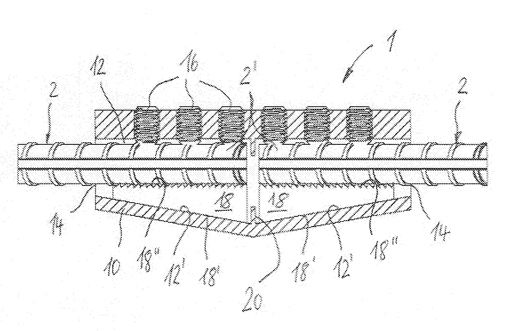
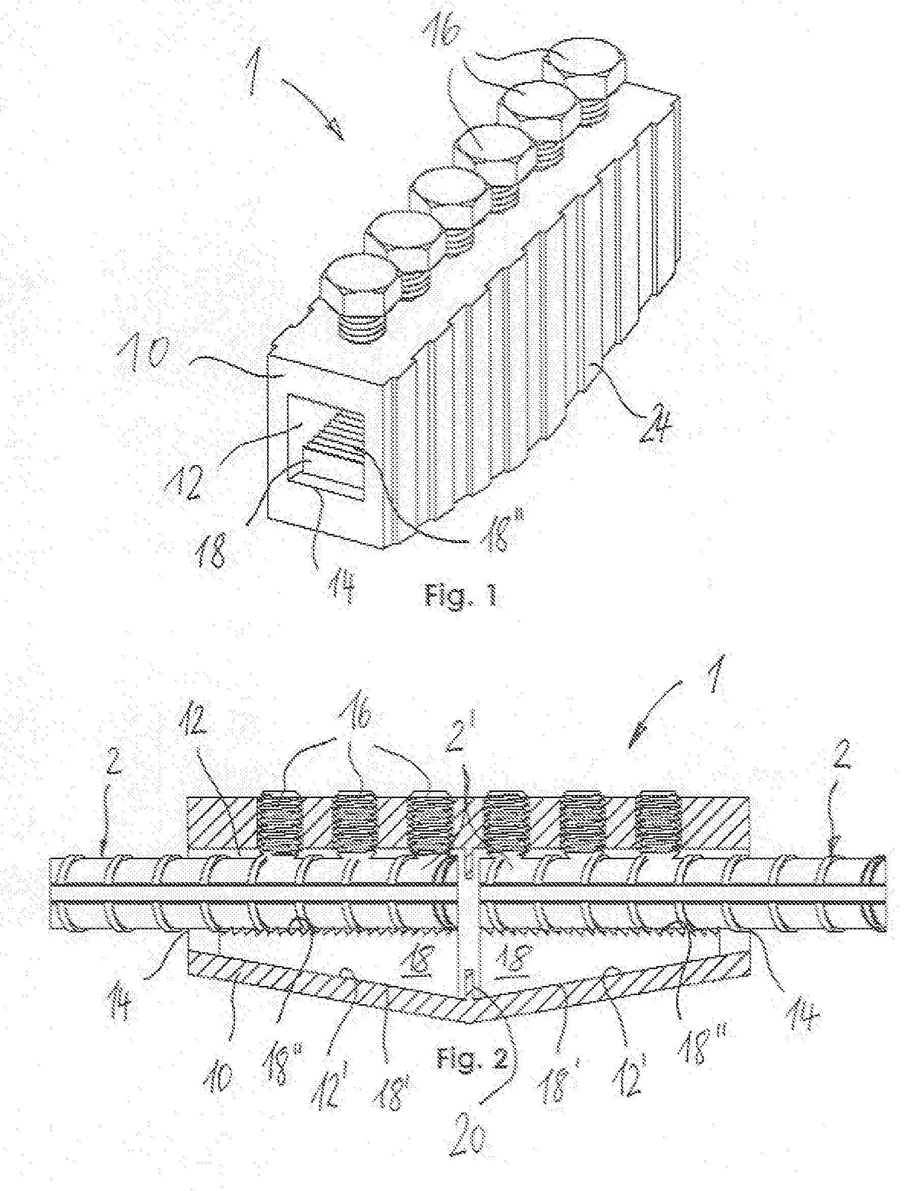
[0046]A device 1 for connecting the ends 2′ of a bar according to the present invention is schematically shown in a perspective view in FIG. 1 as well as in a cross-sectional view in FIG. 2. The device is adapted for connecting rebars and the like end-to-end as they are used in construction, for instance, in reinforced concrete structures. The device 1 comprises a hollow body 10 having an internal cavity 12 which, in the present embodiment, comprises two insertion openings 14 through which a longitudinal axis extends. The direction of extension of the longitudinal axis coincides with the direction of extension of the bars 2 to be connected (FIG. 2).

[0047]Furthermore, the device 1 comprises a plurality of clamping screws 16 which are fitted into threaded holes formed in the hollow body 10. The screws may have a reduced neck so as to produce a defined failure. As can be seen in FIG. 2, the screws 16 are adapted to press on the bars 2 inserted into the hollow body 10.

[0048]Further, the...

second embodiment

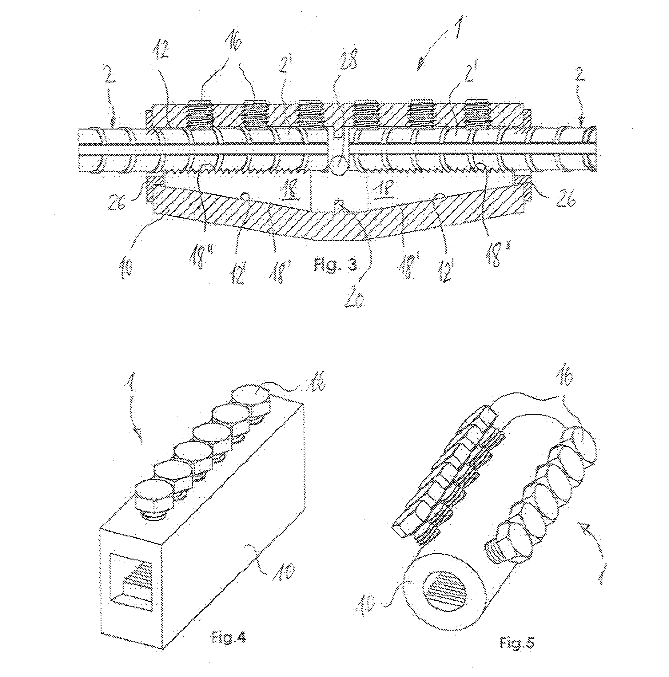
[0053]FIG. 3 relates to a second embodiment for applications where it is necessary to fill up the cavity 12 with a corrosion-protection or binding substance, end caps 26 may be provided to close the spaces at each extremity of the connection, and a hole 28 may be provided in the body 10, through which the substance may be poured or injected.

[0054]FIGS. 4 and 5 show that the external shape of the hollow body 10 may be widely varied within the present invention. Further, the device 1 may comprise one row or also plural rows of screws 16, as shown in FIG. 5.

[0055]Also the shape of the locking elements 18 is not specifically limited in the present invention. Various examples of suitable locking elements 18 are shown in FIGS. 7A to 7G. For instance, the inclined face 18′ may be flat or curved just like the gripping face 18″. Of course, further designs are possible.

[0056]FIG. 8 shows an embodiment which is adapted to connecting bars 2 having different diameters. For this purpose, the lock...

seventh embodiment

[0057]FIGS. 9 and 10 show a sixth and seventh embodiment, respectively, with additional pushing means 22 for pushing the locking elements 18 against the ends 2′ of bars 2 prior to the tightening of screws 16. This feature is illustrated in FIG. 9 with a cam 23 that is rotated around its axis. In FIG. 10 the pushing means 22 comprises a central screw 25 that pushes on the rear faces of the locking elements 18.


PUM


Abstract

A device for connecting bars end-to-end includes a hollow body having an internal cavity with at least one bar insertion opening and a longitudinal axis extending through the at least one insertion opening, and a plurality of radially adjustable clamping elements. The device further includes at least one locking element movably arranged inside the hollow body. The internal cavity of the hollow body has at least one slope inclined relative to the longitudinal axis of the hollow body. The at least one locking element has an inclined face that matches the profile of the at least one slope and a gripping face with at least one protrusion.

Description

CROSS-REFERENCE TO RELATED U.S. APPLICATIONS[0001]Not applicable.STATEMENT REGARDING FEDERALLY SPONSORED RESEARCH OR DEVELOPMENT[0002]Not applicable.NAMES OF PARTIES TO A JOINT RESEARCH AGREEMENT[0003]Not applicable.REFERENCE TO AN APPENDIX SUBMITTED ON COMPACT DISC[0004]Not applicable.BACKGROUND OF THE INVENTION[0005]1. Field of the Invention[0006]The present invention relates to a device for connecting two bars in an end-to-end relationship. The device has a particular application in coupling the ends of reinforcing bars used in structural concrete.[0007]2. Description of Related Art[0008]Including Information Disclosed Under 37 CFR 1.97 and 37 CFR 1.98.[0009]In the art of joining two bars end-to-end in order to extend their continuity, it is known to use a tubular sleeve that receives the end portion of each bar, the sleeve having radially-oriented elements that are forced into the material of the bars in order to lock them. According to one device as disclosed in U.S. Pat. No. 5...

Claims


Application Information

Patent Timeline
Patent Type & Authority Applications(United States)
IPC IPC(8): E04H5/00
CPCE04C5/165
Inventor BRAUN, JEAN-JACQUES
Owner DEXTRA ASIA CO LTD
Why Eureka
Try Eureka