Refrigeration System

a refrigeration system and expansion chamber technology, applied in the field of refrigeration systems, can solve the problems of reducing the power extracted from the expansion chamber, deteriorating the coefficient of performance (cop) of the refrigeration system, etc., and achieve the effect of preventing deterioration in cop, reducing cooling capacity, and reducing cooling costs

Inactive Publication Date: 2008-03-13
DAIKIN IND LTD
View PDF4 Cites 23 Cited by
  • Summary
  • Abstract
  • Description
  • Claims
  • Application Information

AI Technical Summary

Benefits of technology

[0081] According to the first aspect, the provision of the temperature controller (23) capable of controlling the temperature of refrigerant flowing towards the expander (12) enables the control over the specific volume or the flow rate of the refrigerant. Therefore, the flow rate through the compressor (11) and the flow rate through the expander (12) can be balanced even if the operating conditions change. Furthermore, since according to this aspect there is no need for part of the refrigerant to bypass the expander (12) even if the expander (12) falls short of the refrigerant flow rate therethrough, the power extracted from the expander (12) is not reduced. This prevents the COP from being deteriorated.
[0082] According to the second aspect, the temperature controller (23) is configured to have a higher capacity to cool refrigerant flowing towards the expander (12) during the cooling operation than during the heating operation. Therefore, if the refrigeration cycle is designed to balance, in the heating operation, the flow rate through the compressor (11) and the flow rate through the expander (12), the shortage of the refrigerant flow rate through the expander (12) during the cooling operation can be prevented without the refrigerant bypassing the expander (12). Thus, the flow rate through the compressor (11) and the flow rate through the expander (12) can be balanced during both the cooling operation and the heating operation. Hence, the deterioration in COP can be prevented.
[0083] According to the third aspect, since the refrigerant circuit (10) is provided with an internal heat exchanger (23) in which, during the cooling operation, the refrigerant after passing through the heat-source side heat exchanger (21) serving as a gas cooler is cooled by heat exchange with the refrigerant before or after passing through the utilization side heat exchanger (22) serving as an evaporator, the specific volume or the flow rate of refrigerant flowing into the expander (12) can be controlled to balance the flow rate through the compressor (11) and the flow rate through the expander (12). Therefore, the deterioration in COP can be prevented.
[0084] According to the fourth aspect, the internal heat exchanger (23) is configured so that, during the cooling operation, the refrigerant channel (25) through which refrigerant before or after passing through the utilization side heat exchanger (22) serving as an evaporator flows has a higher heat transfer capacity than the refrigerant channel (24) through which refrigerant after passing through the heat-source side heat exchanger (21) serving as a gas cooler flows and that, during the heating operation, the refrigerant channel (24) through which refrigerant before or after passing through the heat-source side heat exchanger (21) serving as an evaporator flows has a lower heat transfer capacity than the refrigerant channel (25) through which refrigerant after passing through the utilization side heat exchanger (22) serving as a gas cooler flows. Therefore, like according to the third aspect, the specific volume or the flow rate of refrigerant flowing into the expander (12) can be controlled to balance the flow rate through the compressor (11) and the flow rate through the expander (12). Therefore, the deterioration in COP can be prevented.
[0085] According to the fifth aspect, since the particular refrigerant channel (25) in the internal heat exchanger (23) is provided with a heat transfer fin (26) so that the amount of heat exchange in the internal heat exchanger (23) during the cooling operation becomes larger than that during the heating operation, the specific volume or the flow rate of refrigerant flowing into the expander (12) can be controlled. Therefore, the flow rate through the compressor (11) and the flow rate through the expander (12) can be balanced during both the cooling operation and the heating operation, thereby preventing the deterioration in COP.
[0086] According to the sixth aspect, since the cooling capacity of the internal heat exchanger (23) during the cooling operation can be higher than that during the heating operation by reversing the circulation direction of refrigerant flowing through the internal heat exchanger (23) at the change from the cooling operation to the heating operation and vice versa, the specific volume or the flow rate of refrigerant flowing into the expander (12) can be controlled. Therefore, the flow rate through the compressor (11) and the flow rate through the expander (12) can be balanced during both the cooling operation and the heating operation, thereby preventing the deterioration in COP.

Problems solved by technology

However, if in the refrigeration system of Patent Document 2 part of refrigerant is caused to flow into the bypass pipe upon change of the operating conditions, power extracted from the expander is reduced, thereby deteriorating the coefficient of performance (COP) of the refrigeration system.

Method used


Image

  • Refrigeration System
  • Refrigeration System
  • Refrigeration System

Examples


embodiment 1

Effects of Embodiment 1

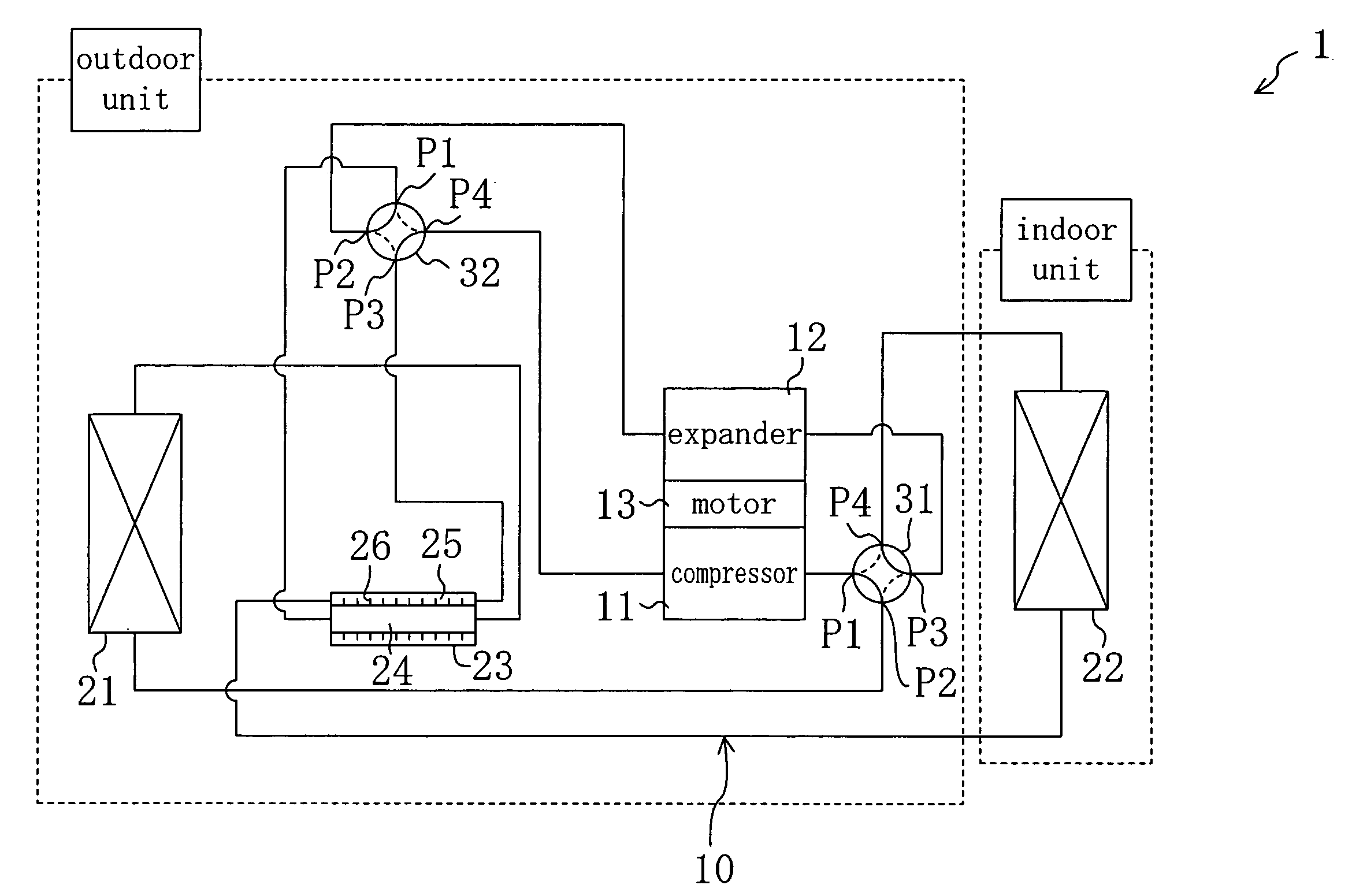
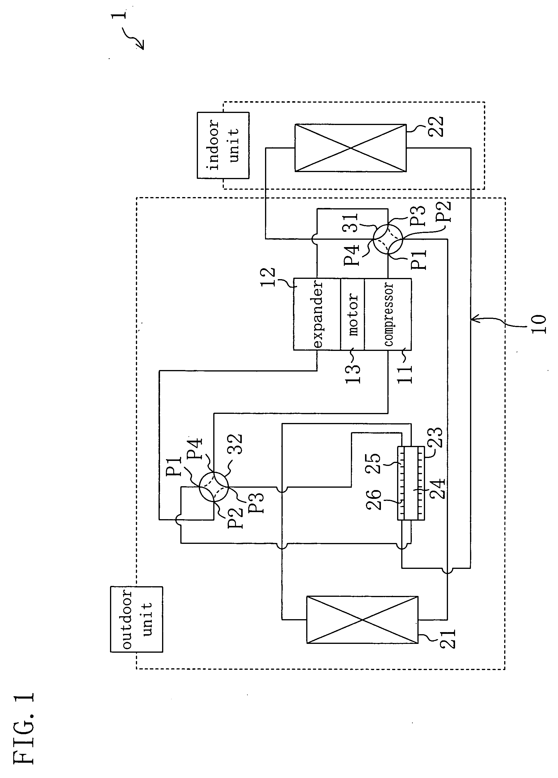
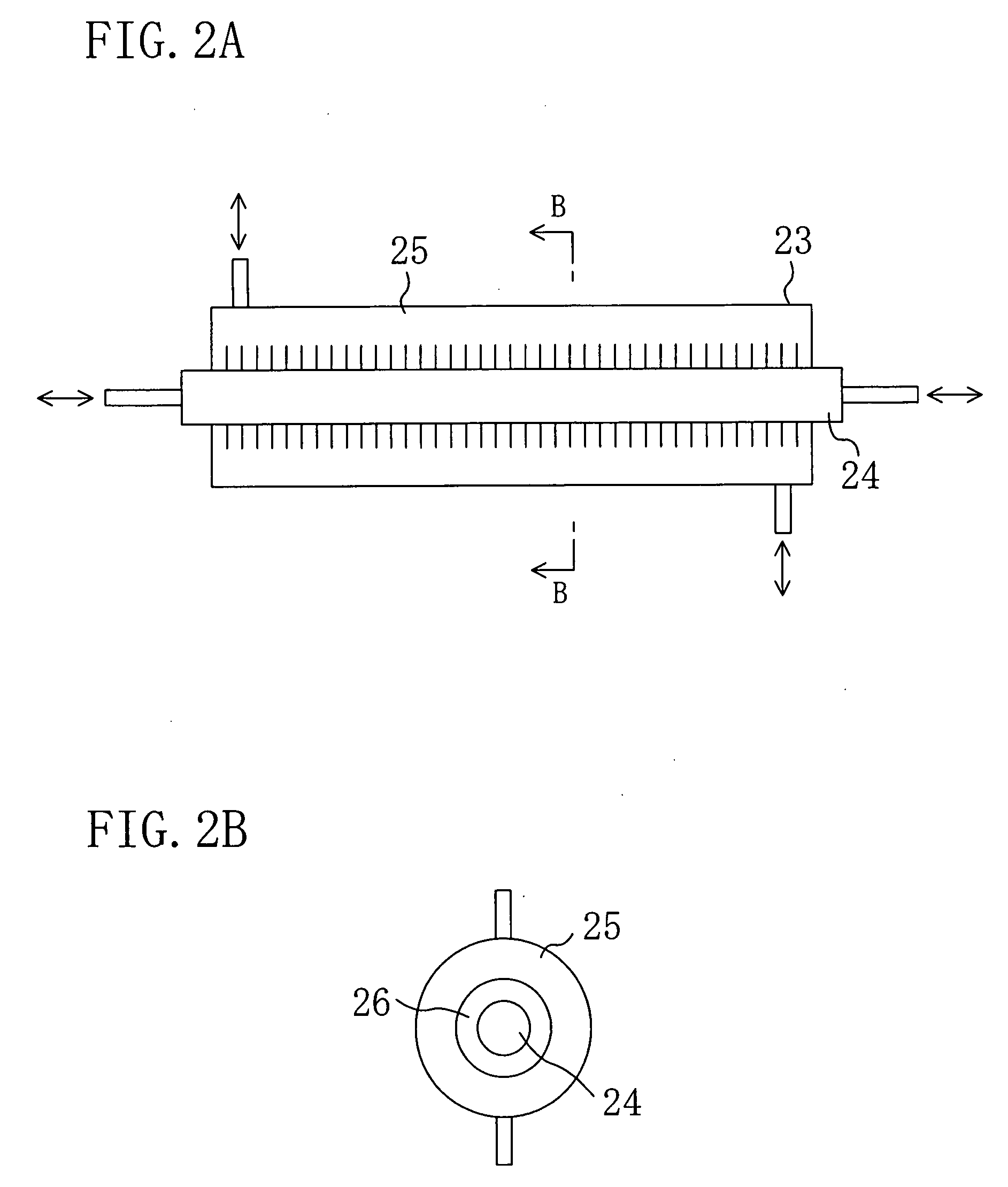
[0214] According to Embodiment 1, in the internal heat exchanger (23) during the cooling operation, refrigerant after passing through the indoor heat exchanger (22) serving as an evaporator flows through the outer channel (25) and refrigerant after passing through 20 the outdoor heat exchanger (21) serving as a gas cooler flows through the inner channel (24). On the other hand, in the internal heat exchanger (23) during the heating operation, refrigerant after passing through the indoor heat exchanger (22) serving as a gas cooler flows through the outer channel (25) and refrigerant after passing through the outdoor heat exchanger (21) serving as an evaporator flows through the inner channel (24). In addition, the outer channel (25) is provided with heat transfer fins (26).

[0215] Thus, during the cooling operation, gas refrigerant after passing through the evaporator flows through the outer channel (25), whereby refrigerant in the inner channel (24) comparativ...

embodiment 2

Effects of Embodiment 2

[0227] Also in Embodiment 2, during the cooling operation, gas refrigerant after passing through the indoor heat exchanger (22) serving as an evaporator flows through the outer channel (25). Therefore, refrigerant in the inner channel (24) comparatively efficiently exchanges heat with refrigerant in the outer channel (25) and the supercritical refrigerant decreases its temperature to reduce its specific volume and then flows in this state into the expander (12). On the other hand, during the heating operation, gas refrigerant after passing through the outdoor heat exchanger (21) serving as an evaporator flows through the inner channel (24). Therefore, refrigerant in the outer channel (25) hardly exchanges heat with refrigerant in the inner channel (24) and the supercritical refrigerant flows into the expander (12) substantially without changing its temperature.

[0228] Since, as described above, the specific volume and flow rate of refrigerant flowing into the ...

embodiment 3

Effects of Embodiment 3

[0240] Also in Embodiment 3, during the cooling operation, gas refrigerant after passing through the indoor heat exchanger (22) serving as an evaporator flows through the outer channel (25). Therefore, refrigerant in the inner channel (24) comparatively efficiently exchanges heat with refrigerant in the outer channel (25) and the supercritical refrigerant decreases its temperature to reduce its specific volume and then flows in this state into the expander (12). On the other hand, during the heating operation, gas refrigerant after passing through the outdoor heat exchanger (21) serving as an evaporator flows through the inner channel (24). Therefore, refrigerant in the outer channel (25) hardly exchanges heat with refrigerant in the inner channel (24) and the supercritical refrigerant flows into the expander (12) substantially without changing its temperature.

[0241] Since, as described above, the specific volume and flow rate of refrigerant flowing into the ...


PUM


Abstract

A refrigeration system includes an internal heat exchanger (23) capable of controlling the temperature of refrigerant flowing towards an expander (12). Upon change of the operating conditions, the internal heat exchanger (23) controls the temperature of the refrigerant to control the specific volume or the flow rate of the refrigerant, thereby eliminating imbalance between the flow rate through a compressor (11) and the flow rate through the expander (12). In a cooling operation in which the refrigerant circulation amount is larger than in a heating operation, the cooling capacity of the internal heat exchanger (23) is enhanced as compared to that in the heating operation, thereby increasing the flow rate of refrigerant into the expander (12) without part of the refrigerant bypassing the expander (12). This prevents the COP of the refrigeration system from being deteriorated.

Description

TECHNICAL FIELD [0001] This invention relates to refrigeration systems including a refrigerant circuit for operating in a vapor compression refrigeration cycle and particularly relates to refrigeration systems in which an expander constituting an expansion mechanism in the refrigerant circuit is mechanically connected to a compressor. BACKGROUND ART [0002] Refrigeration systems have been conventionally known which operate in a refrigeration cycle by circulating refrigerant through a refrigerant circuit that is a closed circuit and are widely used as for air conditioners. As disclosed, for example, in Patent Document 1, there is known a refrigeration system of such kind in which the high-side pressure of a refrigeration cycle is set higher than the critical pressure of the refrigerant. The refrigeration system includes as an expansion mechanism for refrigerant an expander constituted by a scroll fluid machine. The expander is mechanically connected to a compressor by a shaft. Power e...

Claims


Application Information

Patent Timeline
Patent Type & Authority Applications(United States)
IPC IPC(8): F25B9/00F25B29/00F25B41/00F25B43/00
CPCF25B1/04F25B9/008F25B9/06F25B13/00F25B40/00F25B2309/061F28D7/106F25B2313/0272F25B2313/02741F25B2313/02742F25B2400/14F25B2400/23F25B2500/02F25B2313/006F25B11/02F25B1/00
Inventor SAKITANI, KATSUMIMORIWAKI, MICHIOINOKUCHI, YUMESASAKI, YOSHINARI
Owner DAIKIN IND LTD
Why Eureka
Try Eureka