
Magnetic resonance imaging apparatus and magnetic resonance imaging method

Active Publication Date: 2008-03-13
TOKAI UNIV +1
View PDF5 Cites 53 Cited by
  • Summary
  • Abstract
  • Description
  • Claims
  • Application Information

AI Technical Summary

Benefits of technology

[0018]It has been fourthly desired to be able to easily set a labeling region.
[0019]

Problems solved by technology

In spite of an advantage of facilitating the observation of the long-time motion called bulk motion of the cerebrospinal fluid, all of these methods entail a high degree of invasiveness of a test subject.
Moreover, since the radioisotope or contrast media is injected in these methods, the inner pressure of the cerebrospinal fluid might change, which affects an observation target.
Thus, the flow velocity of the blood or cerebrospinal fluid during collection varies every imaging, so that there is a disadvantage that a signal value changes due to effects other than the difference of the inversion time TI or the capability to visualize the blood or cerebrospinal fluid varies every imaging.
Second Problem: in the case where the imaging target is the cerebrospinal fluid, the correlation with the cardiac phase is not necessarily high, and the pulsation regularity of the cerebrospinal fluid tends to be lower than that of blood. Therefore, in the case of the observation target such as the cerebrospinal fluid, there has been a disadvantage that it is not easy to judge whether a change is caused by individual imaging variations or by the variation of the inversion time TI, even if images with the sequentially changed inversion time TI are compared.
Third Problem: in normal labeling methods, there has been a disadvantage that it is not easy to know the motion of the cerebrospinal fluid or blood in the whole two- or three-dimensional region because the labeling region is limited to a straight form.
Fourth Problem: when an imaging section is set out of a normal positioning image, it is not easy to set a labeling region at a proper position because a portion with a suspected lesion of the blood or cerebrospinal fluid is unclear on the positioning image for labeling, and there has been a disadvantage that it is not easy to visualize the motion of the cerebrospinal fluid or blood.
Fifth Problem: there has been a disadvantage that clinical knowledge of the circulatory pathways of the cerebrospinal fluid or blood is required for a user of an apparatus in order to carry out the imaging using labeling, and properly setting imaging conditions is difficult.

Method used


Image

  • Magnetic resonance imaging apparatus and magnetic resonance imaging method
  • Magnetic resonance imaging apparatus and magnetic resonance imaging method
  • Magnetic resonance imaging apparatus and magnetic resonance imaging method

Examples


first embodiment

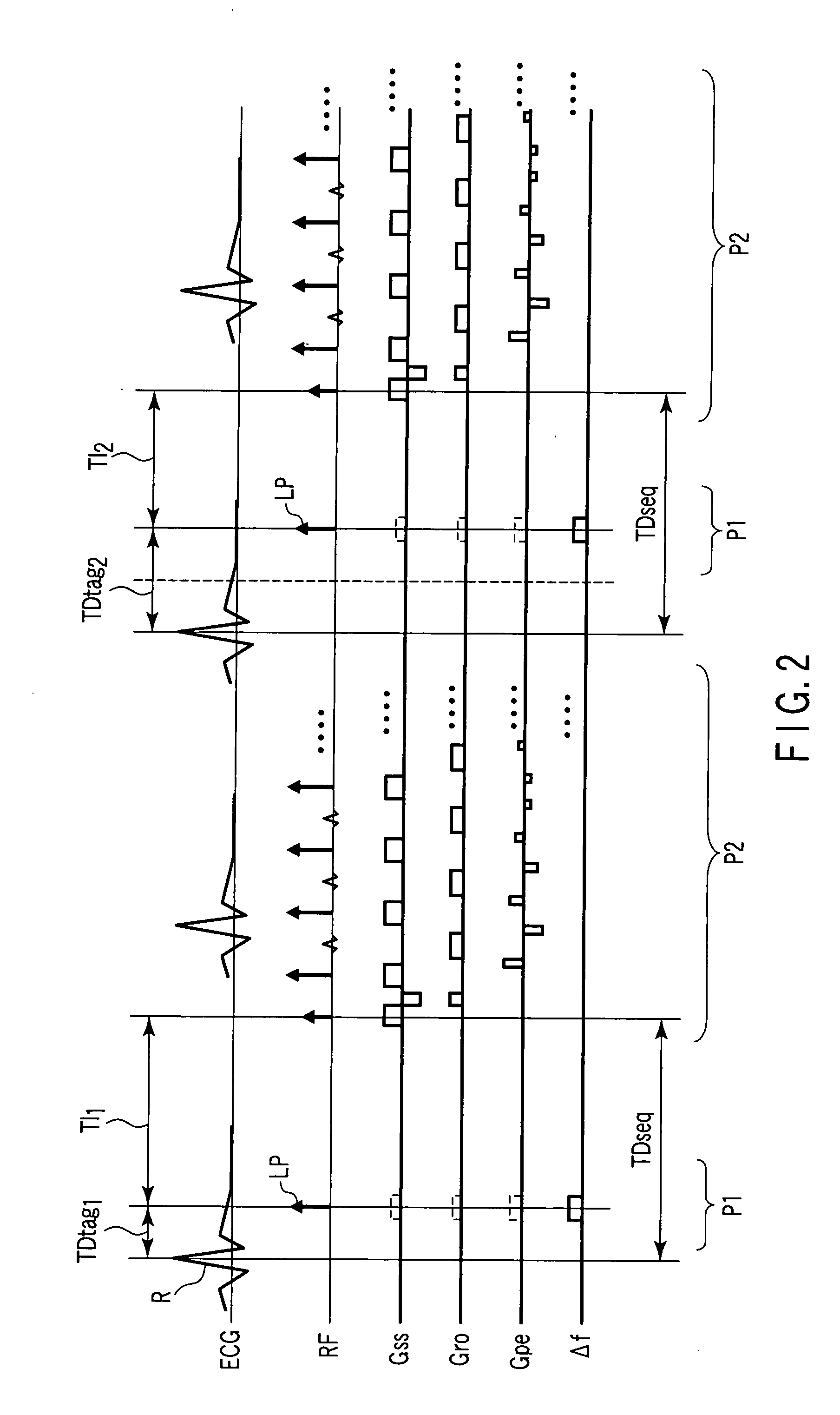
[0082]The first embodiment is described below. The first embodiment corresponds to First Problem.

[0083]FIG. 2 is a diagram showing a pulse sequence in the first embodiment. Waveforms shown in FIG. 2 represent, from top to bottom, an ECG as a synchronization waveform, a radio-frequency (RF) pulse applied to an imaging target, a slice direction gradient magnetic field waveform (Gss), a readout direction gradient magnetic field waveform (Gro), a phase encoding direction gradient magnetic field waveform (Gpe), and a deviation (Δf) of a carrier wave from a center frequency during the application of the radio-frequency pulse. A period P1 is a tag sequence part for labeling blood or cerebrospinal fluid. A period P2 is a main pulse sequence part for imaging. Although a fast spin echo method is employed in this example, it is possible to use any imaging method such as the coherent gradient echo method (the true SSFP method, true FISP or balanced FFE method).

[0084]As apparent from a compariso...

second embodiment

[0097]The second embodiment is described below. The second embodiment corresponds to Second Problem.

[0098]FIG. 5 is a diagram showing a pulse sequence in the second embodiment. Waveforms shown in FIG. 5 represent, from top to bottom, a cerebrospinal fluid pulsation waveform as a synchronization waveform, a radio-frequency (RF) pulse applied to an imaging target, a slice direction gradient magnetic field waveform (Gss), a readout direction gradient magnetic field waveform (Gro), a phase encoding direction gradient magnetic field waveform (Gpe), and a deviation (Δf) of a carrier wave from a center frequency during the application of the radio-frequency pulse. A period P1 is a tag sequence part for labeling blood or cerebrospinal fluid. A period P2 is a main pulse sequence part for imaging. Although the fast spin echo method is employed in this example, it is possible to use any imaging method such as the coherent gradient echo method (the true SSFP method, true FISP or balanced FFE me...

third embodiment

[0114]The third embodiment is described below. The third embodiment corresponds to Second Problem.

[0115]FIG. 11 is a diagram showing a pulse sequence in the third embodiment. Waveforms shown in FIG. 11 represent, from top to bottom, an electrocardiograph (ECG) as a synchronization waveform, a radio-frequency (RF) pulse applied to an imaging target, a slice direction gradient magnetic field waveform (Gss), a readout direction gradient magnetic field waveform (Gro), a phase encoding direction gradient magnetic field waveform (Gpe), and a deviation (Δf) of a carrier wave from a center frequency during the application of the radio-frequency pulse. A period P1 is a tag sequence part for labeling blood or cerebrospinal fluid. A period P2 is a main pulse sequence part for imaging. Although a fast spin echo method is employed in this example, it is possible to use any imaging method such as the coherent gradient echo method (the true SSFP method, true FISP or balanced FFE method).

[0116]As a...


PUM


Abstract

A magnetic resonance imaging apparatus includes an imaging unit which applies a labeling pulse to invert a spin included in a labeling region within part of a imaging region and then collects a echo signal from a time point when an inversion time has passed from the application of the labeling pulse, and a control unit, the control unit controlling the imaging unit so that the echo signal in the imaging region is collected a plurality of times with variations in the inversion time, the control unit also controlling the imaging unit so that a time ranging from a reference time point within a biological signal obtained from a subject to the application of the labeling pulse is a time determined in accordance with the inversion time.

Description

CROSS-REFERENCE TO RELATED APPLICATIONS[0001]This application is based upon and claims the benefit of priority from prior Japanese Patent Application No. 2006-248541, filed Sep. 13, 2006, the entire contents of which are incorporated herein by reference.BACKGROUND OF THE INVENTION[0002]1. Field of the Invention[0003]The present invention relates to a magnetic resonance imaging apparatus and a magnetic resonance imaging method suited to an observation of the dynamic state of a moving material in a body such as blood or cerebrospinal fluid (CSF).[0004]2. Description of the Related Art[0005]A method has been known wherein inversion pulses are applied in order to label, in the form of longitudinal magnetization, an observation target located in a position at a time, and an MRI image is taken after a given time, thereby recognizing the distribution of the labeled observation target (e.g., refer to “Considerations of Magnetic Resonance Angiography by Selective Inversion Recovery,” D. G. N...

Claims


Application Information

Patent Timeline
IPC IPC(8): A61B5/055G01N24/08
CPCA61B5/0263A61B5/7285G01R33/5602G01R33/5614G01R33/5615G01R33/5616G01R33/5676G01R33/56308G01R33/56316G01R33/56333G01R33/56509G01R33/5673G01R33/5617
Inventor YAMADA, SHINYAKANAZAWA, HITOSHIKIMURA, TOKUNORIUMEDA, MASAAKI
Owner TOKAI UNIV
Learn More