Switched-Capacitor Circuit

Inactive Publication Date: 2008-03-13
BOARD OF RGT THE UNIV OF TEXAS SYST
View PDF2 Cites 12 Cited by
  • Summary
  • Abstract
  • Description
  • Claims
  • Application Information

AI Technical Summary

Benefits of technology

[0008]In accordance with a preferred embodiment of the present invention, a switched-capacitor circuit includes a p-channel switched-capacitor integrator and an n-channel switched-capacitor integrator. The p-channel switched-capacitor integrator includes a first set of input transistors controlled by a first set of capacitors and switches. The n-channel switched-capacitor integrator includes a second se

Problems solved by technology

As a result, the amount of circuits and functions th

Method used


Image

  • Switched-Capacitor Circuit
  • Switched-Capacitor Circuit
  • Switched-Capacitor Circuit

Examples


Embodiment Construction

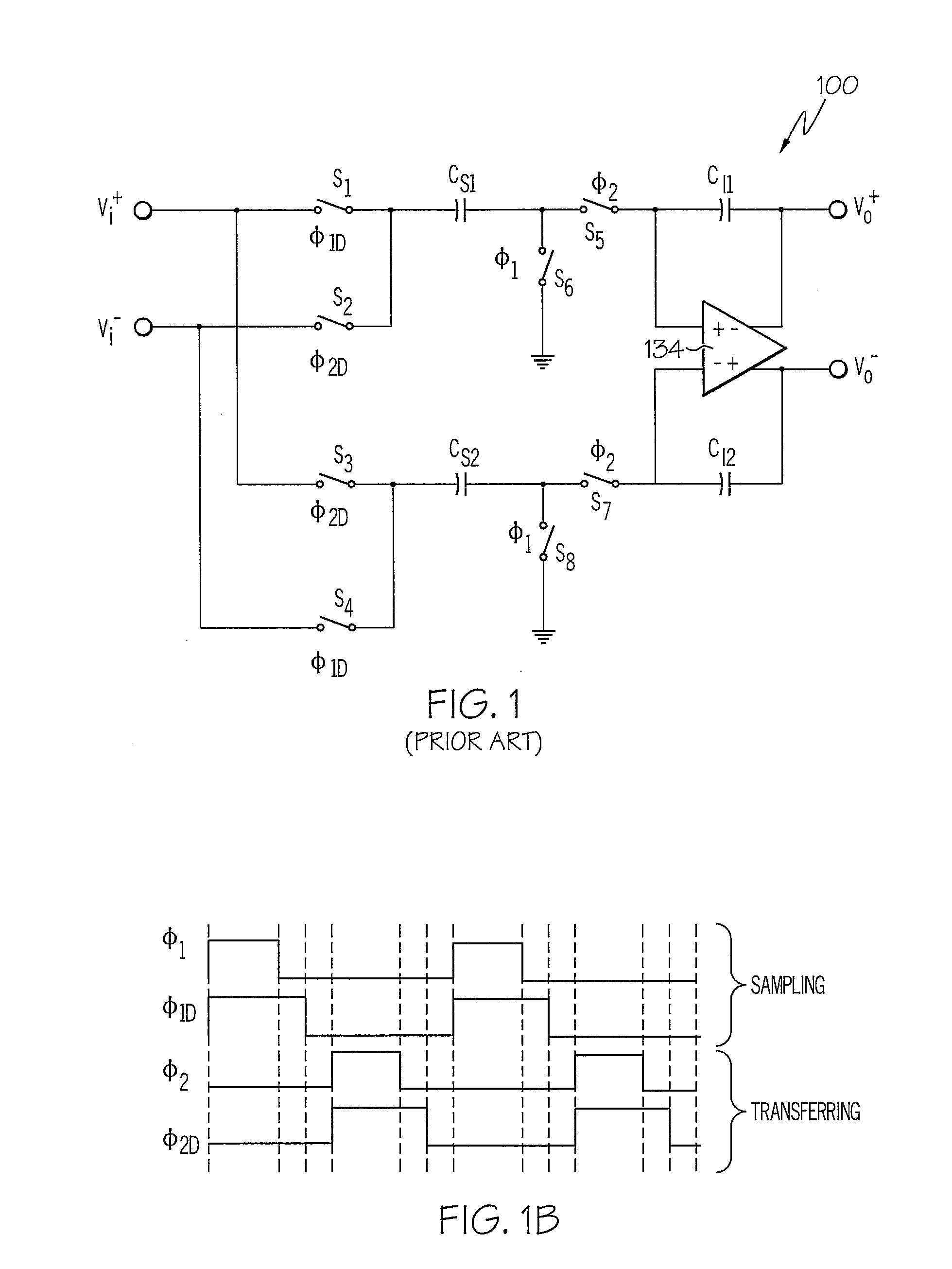
[0016]Referring now to the drawings and in particular to FIG. 1a, there is depicted a schematic diagram of a switched-capacitor circuit, according to the prior art. As shown, a switched-capacitor circuit 100 includes an operational amplifier 134, sampling capacitors CS1, CS2, integration capacitors CI1, CI2, and switches S1, S2, S3, S4, S5, S6, S7 and S8. Operational amplifier 134 can be a telescopic amplifier or a folded-cascode amplifier. Switches S1-S4 are collectively referred to as signal conducting switches, and switches S5-S8 are collectively referred to as summing junction switches.

[0017]Referring now to FIG. 1b, there is illustrated a two-phase non-overlapping clock scheme defined by four clock waveforms: φ1, φ1D, φ2 and φ2D, The position of each of switches S1-S8 from FIG. 1a at any given time is determined by its corresponding one of clock waveforms. For the present embodiment, a switch is open when its corresponding clock waveform is in a “low” state, and a switch is clo...


PUM


Abstract

A low-power switched-capacitor circuit is disclosed. The low-power switched-capacitor circuit includes a p-channel switched-capacitor integrator and an n-channel switched-capacitor integrator. The p-channel switched-capacitor integrator includes a first set of input transistors controlled by a first set of capacitors and switches. The n-channel switched-capacitor integrator includes a second set of input transistors controlled by a second set of capacitors and switches. The p-channel switched-capacitor integrator and the n-channel switched-capacitor integrator function together in a push-pull fashion such that a required transconductance as well as width and drain current of the first and second sets of input transistors are reduced by half of those in a conventional switch-capacitor circuit.

Description

RELATED APPLICATION[0001]The present application claims priority under 35 U.S.C. §119(e)(1) to provisional application No. 60 / 825,230 filed on Sep. 11, 2006, the contents of which are incorporated herein by reference.BACKGROUND OF THE INVENTION[0002]1. Technical Field[0003]The present invention relates to electronic circuits in general, and in particular to switched-capacitor circuits.[0004]2. Description of Related Art[0005]Switched-capacitor circuits are generally employed in a wide range of electronic devices such as analog-to-digital converters, digital-to-analog converters, delta-sigma modulators, filters, power supplies, voltage regulators, etc. In a basic switched-capacitor circuit, an input voltage is sampled onto a sampling capacitor during a first clock phase. During a non-overlapping second clock phase, the charges in the sampling capacitor are transferred to an integration capacitor. The output of the integration capacitor is subsequently fed back to a summing node. The ...

Claims


Application Information

Patent Timeline
IPC IPC(8): G06G7/18
CPCH03F3/005
Inventor CAO, ZHIHENGYAN, SHOULI
Owner BOARD OF RGT THE UNIV OF TEXAS SYST
Why Eureka
Try Eureka