Phase-locked oscillator and multi-radar system using same

Inactive Publication Date: 2008-03-13
FUJITSU LTD
View PDF20 Cites 46 Cited by
  • Summary
  • Abstract
  • Description
  • Claims
  • Application Information

AI Technical Summary

Benefits of technology

[0040]As explained above, by means of a phase-locked oscillator of this invention, even when a VCO circuit having scattering in characteristics or changes with temperature is used, the output frequency due to PLL control can be stabilized, the linearity of output frequency changes due to VCO driving in a PLL open-loop state can be improved, and so the reliability of the phase-locked oscillator can be improved; moreover, the contribution to the spread of FM-CW radar unit and similar usi

Problems solved by technology

Further, in the configuration of the above FIG. 35C, because a PLL is used for feedback of the VCO output modulated by a triangular wave, the modulation characteristics of the VCO output are worsened.
O

Method used


Image

  • Phase-locked oscillator and multi-radar system using same
  • Phase-locked oscillator and multi-radar system using same
  • Phase-locked oscillator and multi-radar system using same

Examples


Embodiment Construction

[0079]Below, preferred aspects of the invention are explained in detail, referring to the attached drawings. Throughout all the drawings, the same symbols denote the same or equivalent portions.

[0080](Phase-Locked Oscillator)

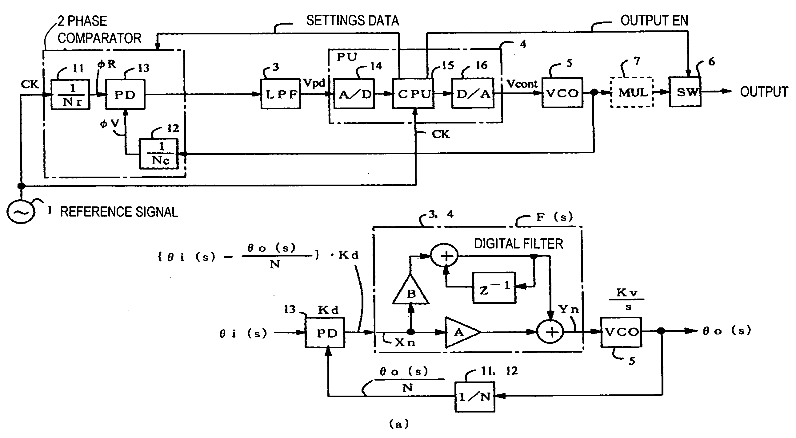
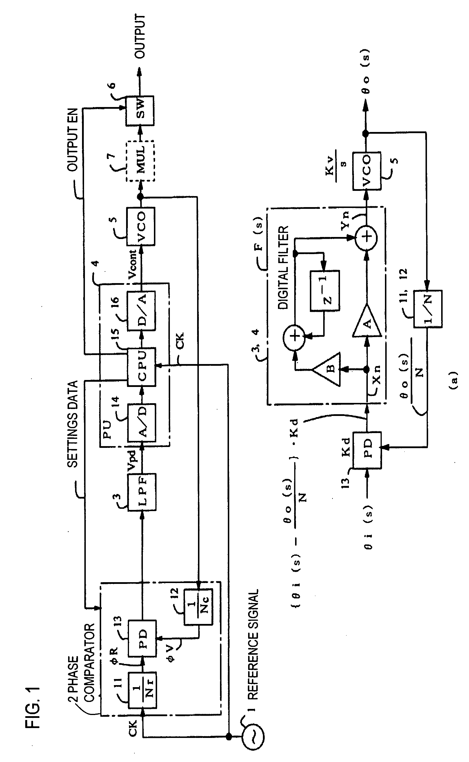
[0081]FIG. 1 is a block diagram of the phase-locked oscillator of a first aspect. In the figure, a reference number 1 is a clock oscillator which generates a PLL reference clock signal CK, a reference number 2 is a phase detector comprised by the PLL loop, a reference number 11 is a variable frequency divider for the clock signal CK, a reference number 12 is a VCO output variable frequency divider, a reference number 13 is a phase detector (PD) which compares the phases of the two frequency-divided outputs φR and φV, a reference number 3 is a low-pass filter (LPF) which integrates the phase error signal of the output of the PD 13, a reference number 4 is a processor unit (PU) which is equivalent to the controller of the invention, a reference number 14 is an A / D...


PUM


Abstract

In a multi-radar system, configured comprising a plurality of radar units which generate and output signals the frequency of which increases and decreases periodically, each radar unit generates and outputs signals synchronized with a prescribed sync signal, such that the upper limit and lower limit of the periodically increasing and decreasing frequency is different for the signals of each radar unit, and moreover the timing of the upper limit and lower limit of the signals substantially coincide. By this means, the frequency intervals between signals can be reduced, and more channels can be set, without causing radio wave interference.

Description

CROSS-REFERENCE TO RELATED APPLICATIONS[0001]This application is based upon and claims the benefit of priority from the prior Japanese Patent Application No. 2006-247416, filed on Sep. 12, 2006 and the prior Japanese Patent Application No. 2007-148188, filed on Jun. 4, 2007, the entire contents of which are incorporated herein by reference.BACKGROUND OF THE INVENTION[0002]1. Field of the Invention[0003]This invention relates to a phase-locked oscillator and to a multi-radar system using the phase-locked oscillator. In particular, this invention is suitable for use in a phase-locked oscillator suitable for use in FM-CW radar or other RF-band oscillators, and for use in a multi-radar system using the phase-locked oscillator.[0004]2. Description of the Related Art[0005]FIG. 35A-35C are figures explaining technology of the prior art; FIG. 35A shows the frequency modulator of FM-CW radar of the prior art. In the basic configuration of the FM-CW method, a triangular-wave modulation signal...

Claims


Application Information

Patent Timeline
IPC IPC(8): G01S13/00H03L7/08
CPCG01S7/023G01S7/032G01S7/35G01S7/4008H03L7/23G01S13/931H03L7/093H03L7/18G01S13/34G01S7/0232G01S7/0235
Inventor HONGO, HIRONOBU
Owner FUJITSU LTD
Why Eureka
Try Eureka