Ring oscillator and semiconductor integrated circuit and electronic device including the same

a technology of integrated circuits and oscillators, which is applied in the direction of oscillator generators, logic circuit pulse generation, etc., can solve the problems of blocking the reduction of power consumption of microcomputers, no cost merit above the way of providing an external quartz oscillator to obtain an operation clock signal for a microcomputer, etc., to achieve sufficient oscillation frequency precision, improve the yield of semiconductor integrated circuits, and excellent robustness

Inactive Publication Date: 2008-03-13
COLLABO INNOVATIONS INC
View PDF5 Cites 33 Cited by
  • Summary
  • Abstract
  • Description
  • Claims
  • Application Information

AI Technical Summary

Benefits of technology

[0020] According to the invention described above, parameters for correcting deflections in the oscillation frequency of ring oscillators can be stored for individual products, and thus any ring oscillator can generate uniform highly-precise oscillating signals irrespective of fabrication variations, if any. This permits improvement in the yield of semiconductor integrated circuits provided with such ring oscillators.
[0021] As described above, according to the present invention, ring oscillators that are excellent in robustness against variations in power supply voltage, ambient temperature and the like and can attain suff...

Problems solved by technology

In view of the present situation that microcomputers have become inexpensive, however, the above way of providing an external quartz oscillator to obtain an operation clock signal for a microcomputer has no cost merit.
Also, an input buf...

Method used


Image

  • Ring oscillator and semiconductor integrated circuit and electronic device including the same
  • Ring oscillator and semiconductor integrated circuit and electronic device including the same
  • Ring oscillator and semiconductor integrated circuit and electronic device including the same

Examples


embodiment 1

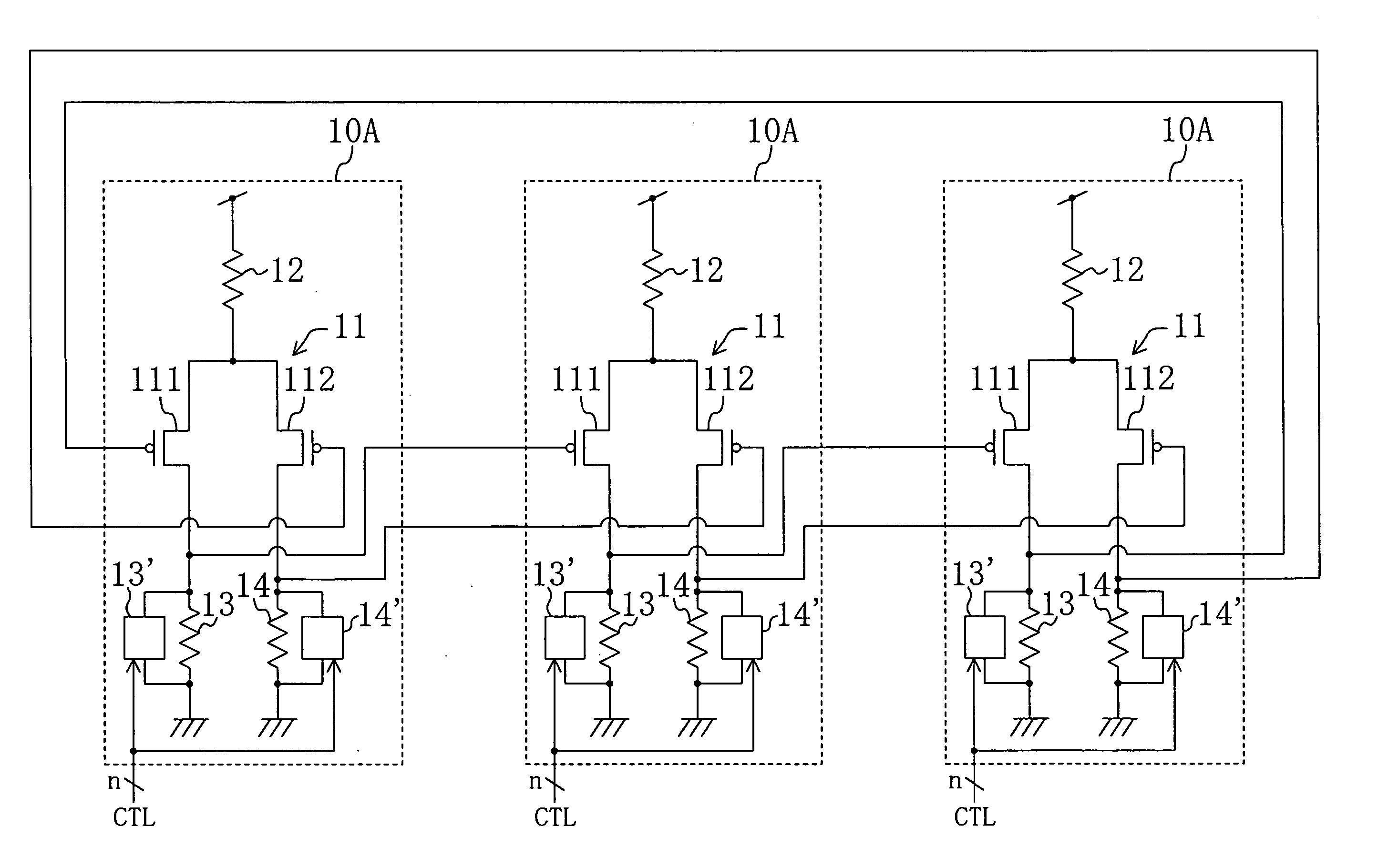
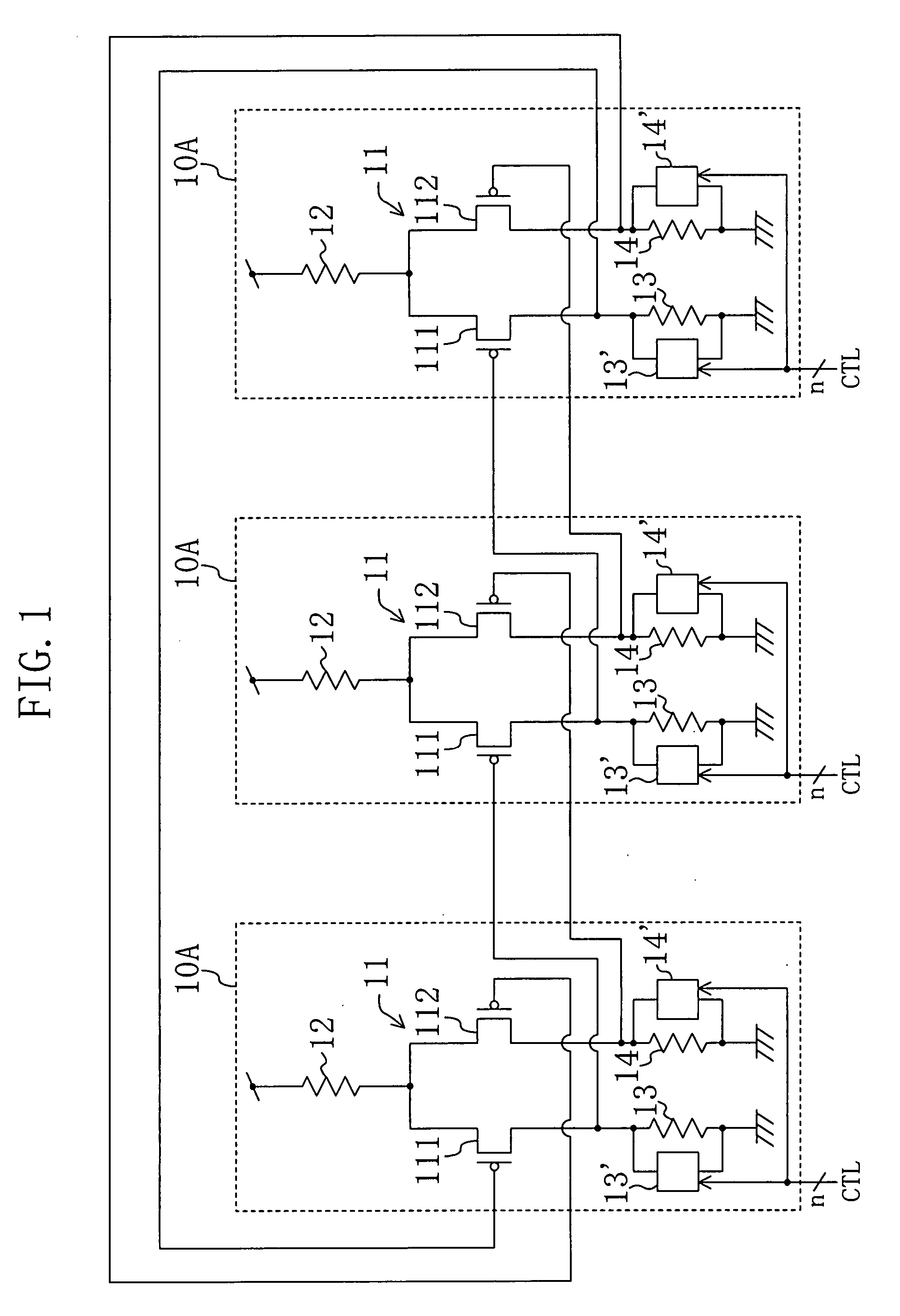
[0039]FIG. 1 shows a configuration of a ring oscillator of Embodiment 1. The ring oscillator of this embodiment is composed of three differential amplifier circuits 10A connected in a loop. Each of the differential amplifier circuits 10A includes a differential transistor pair 11, resistances 12, 13 and 14 and passive circuits 13′ and 14′. The differential transistor pair 11 is composed of PMOS transistors 111 and 112 whose sources are connected to each other and whose gates receive a differential signal. The resistance 12 is connected to the junction point of the PMOS transistors 111 and 112 at one terminal and to the power supply voltage node at the other terminal. The resistance 13 is connected to the drain of the PMOS transistor 111 at one terminal and to the ground voltage node at the other terminal. The resistance 14 is connected to the drain of the PMOS transistor 112 at one terminal and to the ground voltage node at the other terminal. The passive circuits 13′ and 14′ are re...

embodiment 2

[0046]FIG. 5 shows a configuration of a ring oscillator of Embodiment 2 of the present invention. The ring oscillator of this embodiment is composed of three differential amplifier circuits 10B connected in a loop. Each of the differential amplifier circuits 10B is different from the differential amplifier circuit 10A shown in FIG. 1 in that the passive circuits 13′ and 14′ are omitted and instead a passive circuit 12′ is provided in parallel with the resistance 12.

[0047] The passive circuit 12′ can be made of the variable resistance circuit shown in FIG. 3. With the passive circuit 12′ made of the variable resistance circuit being connected in parallel with the resistance 12, the combined resistance value becomes small. This increases the capacity of current supply to the resistances 13 and 14, and thus the oscillation frequency of the ring oscillator becomes higher. The oscillation frequency of the ring oscillator will further become higher as the resistance value of the passive ...

embodiment 3

[0049]FIG. 6 shows a configuration of a ring oscillator of Embodiment 3 of the present invention. The ring oscillator of this embodiment is composed of three differential amplifier circuits 10C connected in a loop. Each of the differential amplifier circuits 10C is different from the differential amplifier circuit 10A shown in FIG. 1 in that NMOS transistors 15 and 16 are respectively provided in place of the circuit portion composed of the resistance 13 and the passive circuit 13′ and the circuit portion composed of the resistance 14 and the passive circuit 14′ and that a resistance 17 and a passive circuit 17′ are newly provided to be connected to the junction point of the PMOS transistor 111 and the NMOS transistor 15 at one terminal and to the junction point of the PMOS transistor 112 and the NMOS transistor 16 at the other terminal.

[0050] A same signal is supplied to the gate of the NMOS transistor 15 and the gate of the PMOS transistor 111. Likewise, a same signal is supplied...


PUM


Abstract

A differential amplifier circuit includes: a differential transistor pair composed of first and second transistors; a first resistance connected to a junction point of the first and second transistors at one terminal and to a first voltage node at the other terminal; second and third resistances provided between the first and second transistors, respectively, and a second voltage node; and first and second passive circuits respectively connected to the second and third resistances, the load characteristics of the passive circuits changing according to a control signal supplied. A ring oscillator is composed of a plurality of such differential amplifier circuits connected in a loop.

Description

BACKGROUND OF THE INVENTION [0001] 1. Field of the Invention [0002] The present invention relates to a ring oscillator, and more particularly to an oscillator for generating an operation clock signal used in microcomputers and the like and a semiconductor integrated circuit and an electronic device including the same. [0003] 2. Description of the Related Art [0004] In microcomputers and the like, a desired operation frequency is generally obtained by lowering the frequency of an original clock signal inputted from an external quartz oscillator with an internal frequency divider. In view of the present situation that microcomputers have become inexpensive, however, the above way of providing an external quartz oscillator to obtain an operation clock signal for a microcomputer has no cost merit. Also, an input buffer section of a microcomputer that receives an original clock signal from an external quartz oscillator is still required to operate at high speed, and this has become a cau...

Claims


Application Information

Patent Timeline
IPC IPC(8): H03K3/03
CPCH03K3/0322H03K5/133H03L7/0995H03K2005/00208H03L1/00H03K2005/00058H03K3/354
Inventor RAITA, KAZUHISAYAMANE, ICHIROKITAO, YOSHITAKAHAMAGUCHI, TOSHIFUMIINAUCHI, TAKAHIRO
Owner COLLABO INNOVATIONS INC
Why Eureka
Try Eureka