
Disc Recording Medium, Disc Drive, and Manufactuing Method of Optical Disc

a technology of disc recording medium and manufacturing method, which is applied in the direction of optical recording/reproducing/erasing methods, record information storage, instruments, etc., can solve the problems of difficult spiral cutting of the surface of the recording medium into grooves, increasing the degree of difficulty in the formation of grooves, and limiting the recording density of an hdd. to 100 to 300 gbpsi. , to achieve the effect of stably performing recording processing

Inactive Publication Date: 2008-03-13
SONY CORP
View PDF5 Cites 3 Cited by
  • Summary
  • Abstract
  • Description
  • Claims
  • Application Information

AI Technical Summary

Benefits of technology

The present invention provides a disc recording medium and a disc drive that can record and play high-density information using near-field light. The disc recording medium has guide grooves for tracking control and concave portions on its surface in correspondence with the guide grooves. The guide grooves help in recording information on the recording layer using near-field light. The concave portions on the outermost surface of the disc recording medium make it easy to acquire the signal of the guide grooves. The guide grooves are formed into a concave shape and a protection film is formed along the grooves. This increases the thickness of the air layer, making it easy to acquire the signal of the guide grooves. The recording surface is formed into a convex shape, and guide grooves are formed at predetermined pitches for receiving a multibeam. This allows a recording area to be widely formed at the portion near the lens, making it easy to form the near-field. The present invention is useful to an optical disc that performs recording / reproduction of information using near-filed light based on a multibeam.

Problems solved by technology

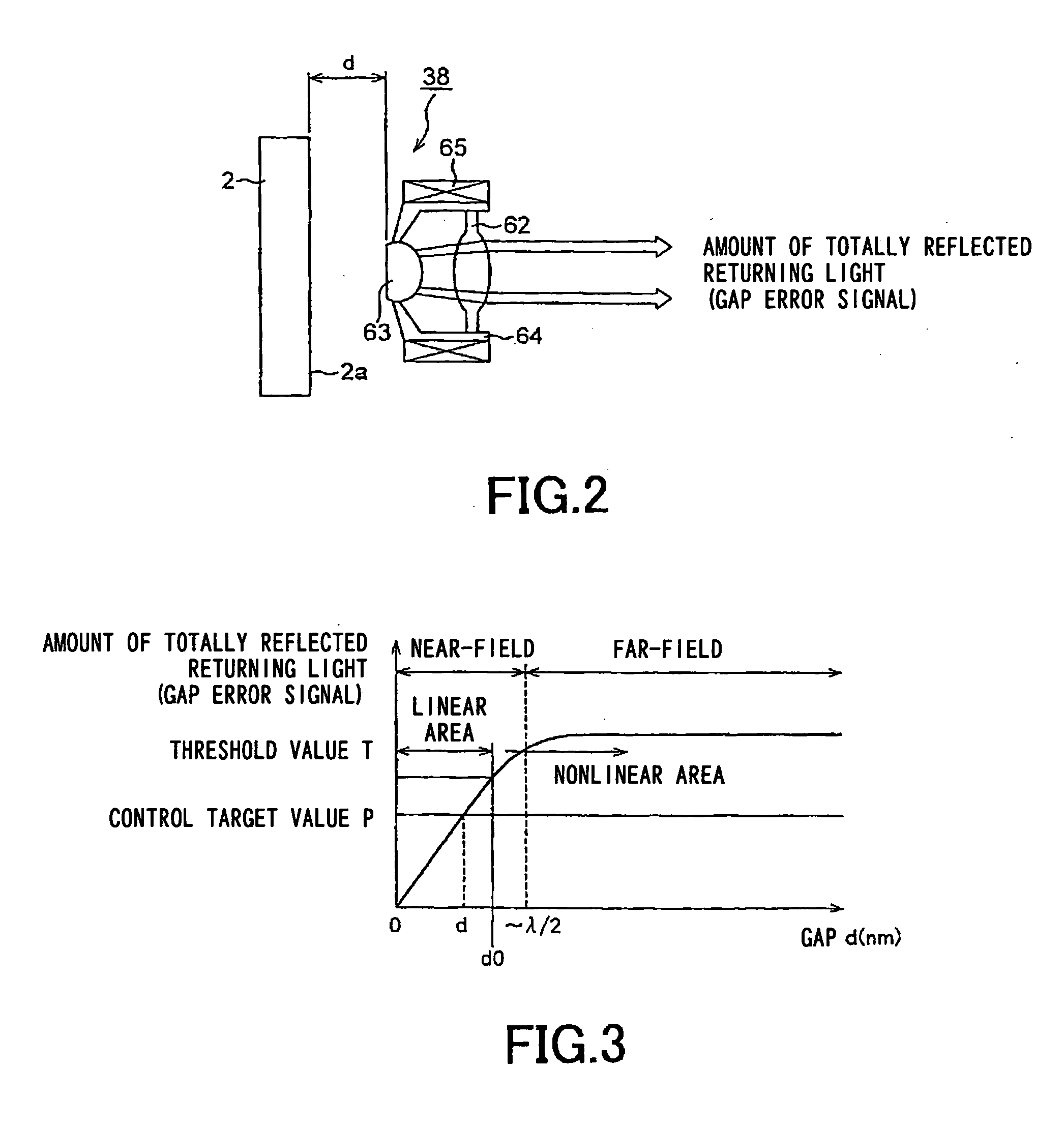
It is said that a recording density of an HDD is limited to 100 to 300 Gbpsi due to a superparamagnetic effect and difficulty in controlling the gap width of a magnetic head, and an optical assist magnetic recording technology is now expected to push the limit.
However, the reality is that it is not easy to spirally cut the surface of a recording medium into grooves at fine pitches in correspondence with the many light spots.
. . , the degree of difficulty in the formation of the grooves increases proportionately.
Therefore, the tilt or displacement of the objective lens may become a barrier in achieving more reliable recording / reproducing processing.

Method used


Image

  • Disc Recording Medium, Disc Drive, and Manufactuing Method of Optical Disc
  • Disc Recording Medium, Disc Drive, and Manufactuing Method of Optical Disc
  • Disc Recording Medium, Disc Drive, and Manufactuing Method of Optical Disc

Examples


Embodiment Construction

[0024] An embodiment of the present invention will be described in detail below with reference to the accompanying drawings.

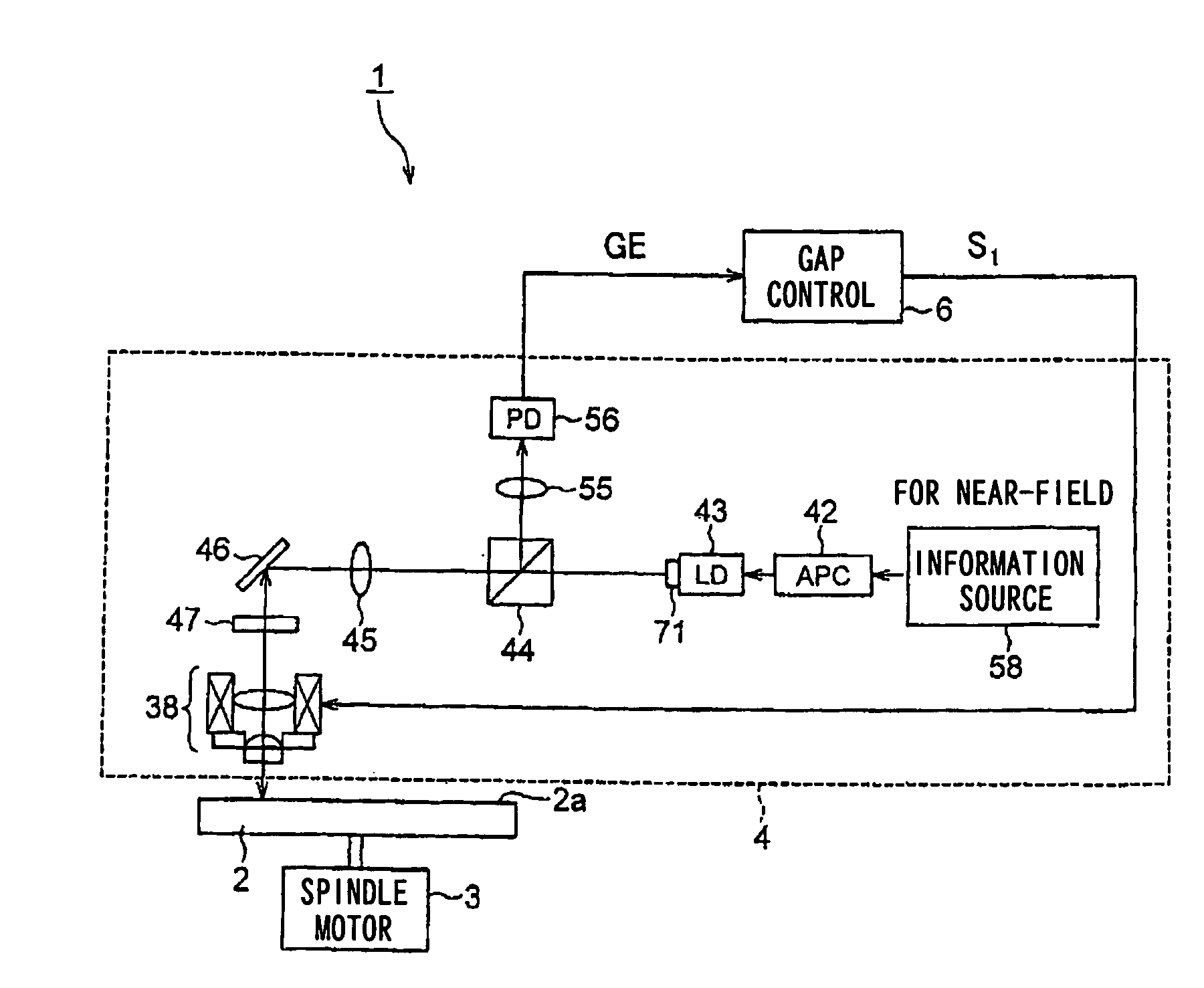
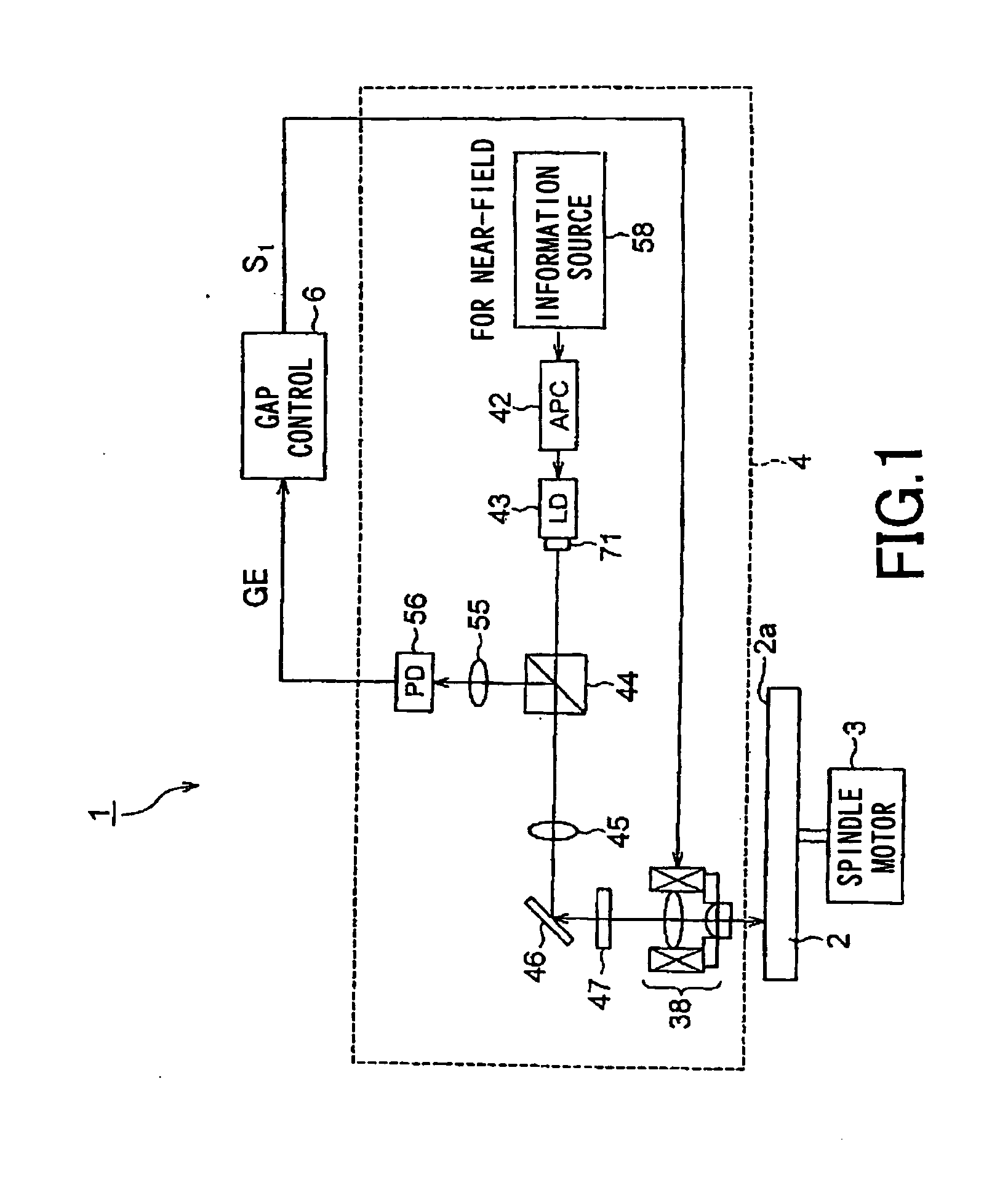
[0025] A disc drive according to the present invention will be described first. As shown in FIG. 1, an optical recording apparatus 1, which is an apparatus detachably receiving an optical disc 2 therein as a recording medium, includes: a spindle motor 3 for rotating the optical disc 2 to be detachably mounted in the optical recording apparatus 1; an optical head 4 for irradiating a signal recording surface 2a of the optical disc 2 with laser light and detecting the returning laser light reflected by the signal recording surface 2a of the optical disc 2; and a gap controller 6 for generating a control signal S1 based on the returning laser light detected by the optical head 4.

[0026] A disc table on which the optical disc 2 is mounted is integrally attached to the spindle motor 3. The spindle motor 3 rotates a drive shaft at, e.g., CLV (Constant Liner Velocity)...


PUM

PropertyMeasurementUnit
widthaaaaaaaaaa
recording densityaaaaaaaaaa
gap widthaaaaaaaaaa

Abstract

The present invention relates to an optical disc on which an information signal can be rewritten. Guide grooves (81a) for tracking control are formed on respective tracks of the rewritable area where an information signal can be rewritten. A recording layer (83) onto which an information signal is to be written is laminated on a substrate on which the guide grooves (81a) have been formed. The information signal can be rewritten on the recording layer (83) at least in the rewritable area using near-field light based on multibeam. Concave portions (85a) are formed on the outermost surface of the disc recording medium in correspondence with the positions of the guide grooves (81a).

Description

[0001] than the DVD has now been developed. At the same time, the recording density of an HDD (Hard Disc Drive) is increasing year by year. [0002] Along with the digitization and increase in resolution of image information and the improvement of communication performance of an optical communication, there has recently been an increased demand for further improvement of recording density and recording capacity of storage. A recording density of 1 Tbits / (inch)2 is expected in 2010. [0003] It is said that a recording density of an HDD is limited to 100 to 300 Gbpsi due to a superparamagnetic effect and difficulty in controlling the gap width of a magnetic head, and an optical assist magnetic recording technology is now expected to push the limit. [0004] In the field of an optical recording medium, an optical recording using near-field light is expected to improve the recording density. The near-field light is non-propagation light existing within the area less than the diffraction limi...

Claims


Application Information

Patent Timeline
Patent Type & Authority Applications(United States)
IPC IPC(8): G11B19/00
CPCG11B7/006G11B7/1374G11B7/26G11B7/2405G11B7/24082G11B7/1387
Inventor NAKAOKI, ARIYOSHIYAMAMOTO, MASANOBUSAITO, KIMIHIRO
Owner SONY CORP
Learn More