Surgical universal positioning block and tool guide

a technology for positioning blocks and tools, applied in the field of surgical tools for knee surgery, can solve the problems of sterilization problems, bacteria can build up inside the bore, and the spring and inside bore of the mechanism becomes difficult to clean,

Active Publication Date: 2008-03-13
ORTHOSOFT ULC
View PDF21 Cites 26 Cited by
  • Summary
  • Abstract
  • Description
  • Claims
  • Application Information

AI Technical Summary

Benefits of technology

[0014] Accordingly, it is an object of the present invention to provide a positioning block for total knee replacement surgery having improved mobility.
[0016] It is another object of the present invention to provide an improved distal drill and / or cutting guide for use in total knee replacement surgery, being adaptable to different implant types and capable of simplified location of the distal cut reference.
[0017] It is another object of the present invention to provide a surgical tool guide having a biased pawl mechanism that can be easily dismantled for cleaning.
[0018] There is therefore provided, in accordance with the present invention, a method of installing a surgical positioning block on a bone element, the positioning block having a reference surface and being operatively engageable with a cutting tool, the method comprising fastening the positioning block to the bone element; determining a desired position of the reference surface of the positioning block relative to the bone element; adjusting at least one of the position and orientation of the positioning block, until the reference surface is in the desired position; and using the reference surface in the desired position as a reference for locating the cutting tool in a predetermined location on the bone element, such that a cut can be made in the bone element at the predetermined location.
[0020] There is also provided, in accordance with the present invention, a computer assisted total knee replacement surgery system comprising: a positioning block being fastenable to a bone element; means for determining the position and orientation of the positioning block relative to the bone element; the positioning block having a reference surface and being operatively engageable with a cutting tool; means for identifying a desired position of the positioning block relative to the bone element, such that the reference surface is located in a position relative to the bone element whereby the cutting tool, disposed in a known position relative to the reference surface, is located in a selected position relative to the bone element, such that a cut can be made in the bone element at the selected position; and a display capable of indicating when the desired position of the positioning block is reached.
[0023] There is also provided, in accordance with the present invention, a surgical tool guide for preparing the femoral portion of a knee in a total knee replacement surgery, comprising: a guide block having at least one of a drill guide hole and a distal cuffing guide slot, and comprising an elastically deflectable blade spring; an anteriorly mounted platform, comprising a toothed rack and providing support for the guide block such that proximal-distal sliding displacement of the guide block thereon is permitted; the platform being adapted for mounting to a femoral reference positioning guide member distally fastened to the femur; the guide block and the platform having substantially seamless surfaces that are at least one of substantially exposed or exposable, such that the surfaces can easily be pressure cleaned and autoclaved to remove biological matter therefrom; and a pawl being normally biased by the blade spring such that it is in engagement with the toothed rack on the platform; whereby the guide block is displaceable relative to the platform when the biased pawl is disengaged from the toothed rack and fixed relative thereto when the pawl is engaged with the toothed rack.

Problems solved by technology

This often causes sterilization problems, as cleaning the spring and inside bore of the mechanism becomes difficult because the captive plunger can not be removed.
As a result, bacteria can build up inside the bore, and can not be easily cleaned out and sterilized.
This becomes a major problem as cleanliness is paramount in surgical environments.

Method used


Image

  • Surgical universal positioning block and tool guide
  • Surgical universal positioning block and tool guide
  • Surgical universal positioning block and tool guide

Examples


Embodiment Construction

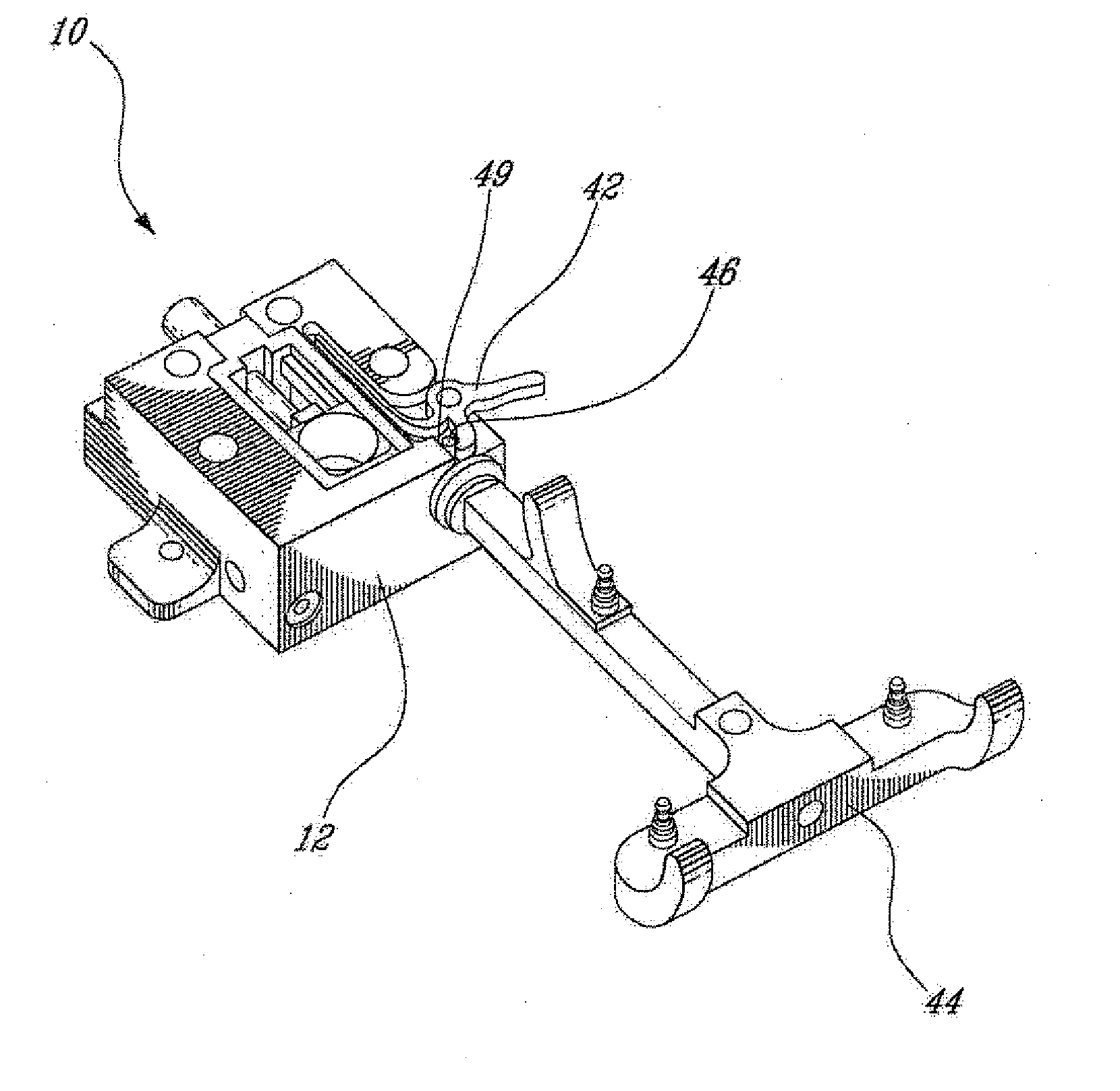
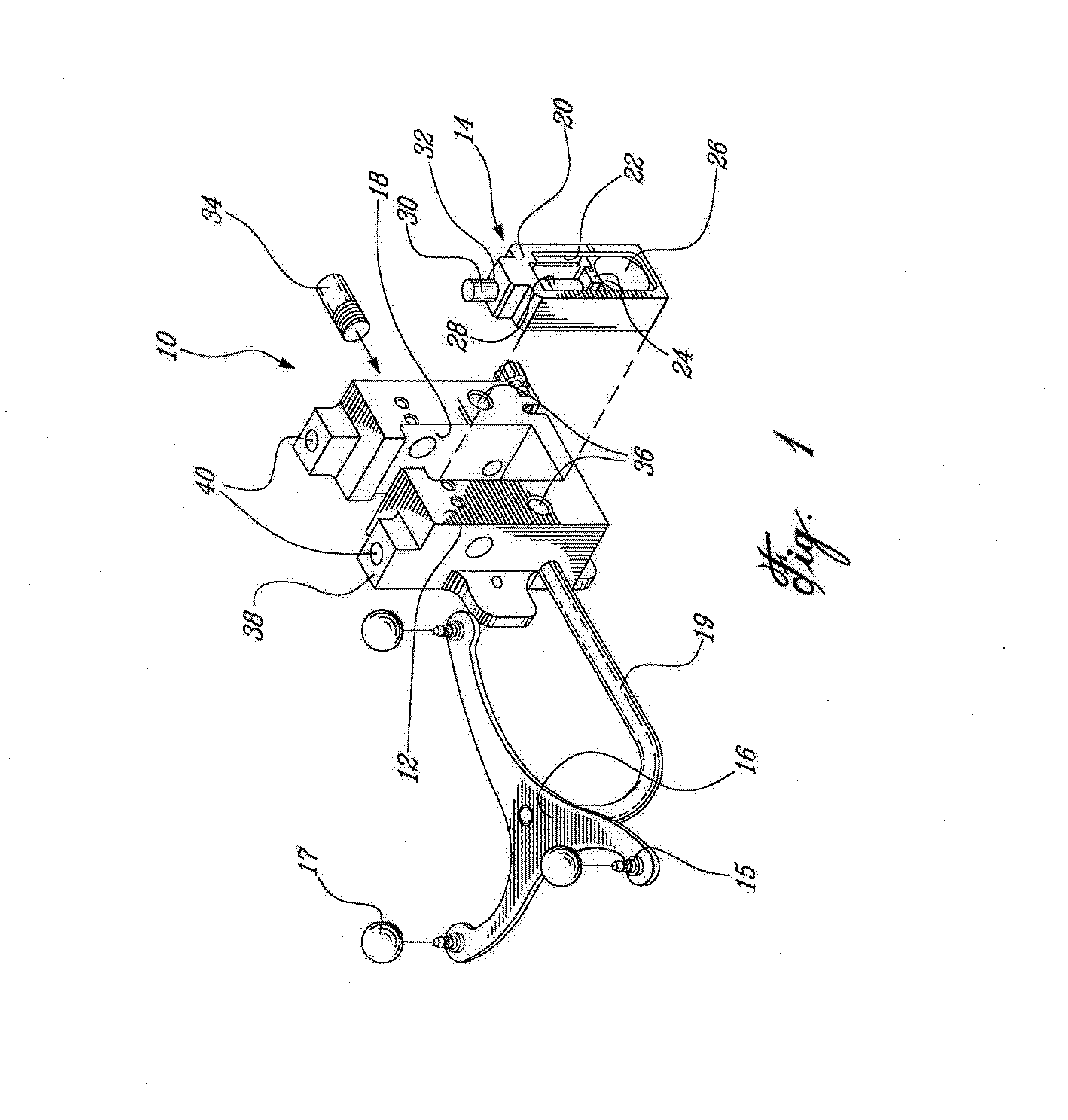
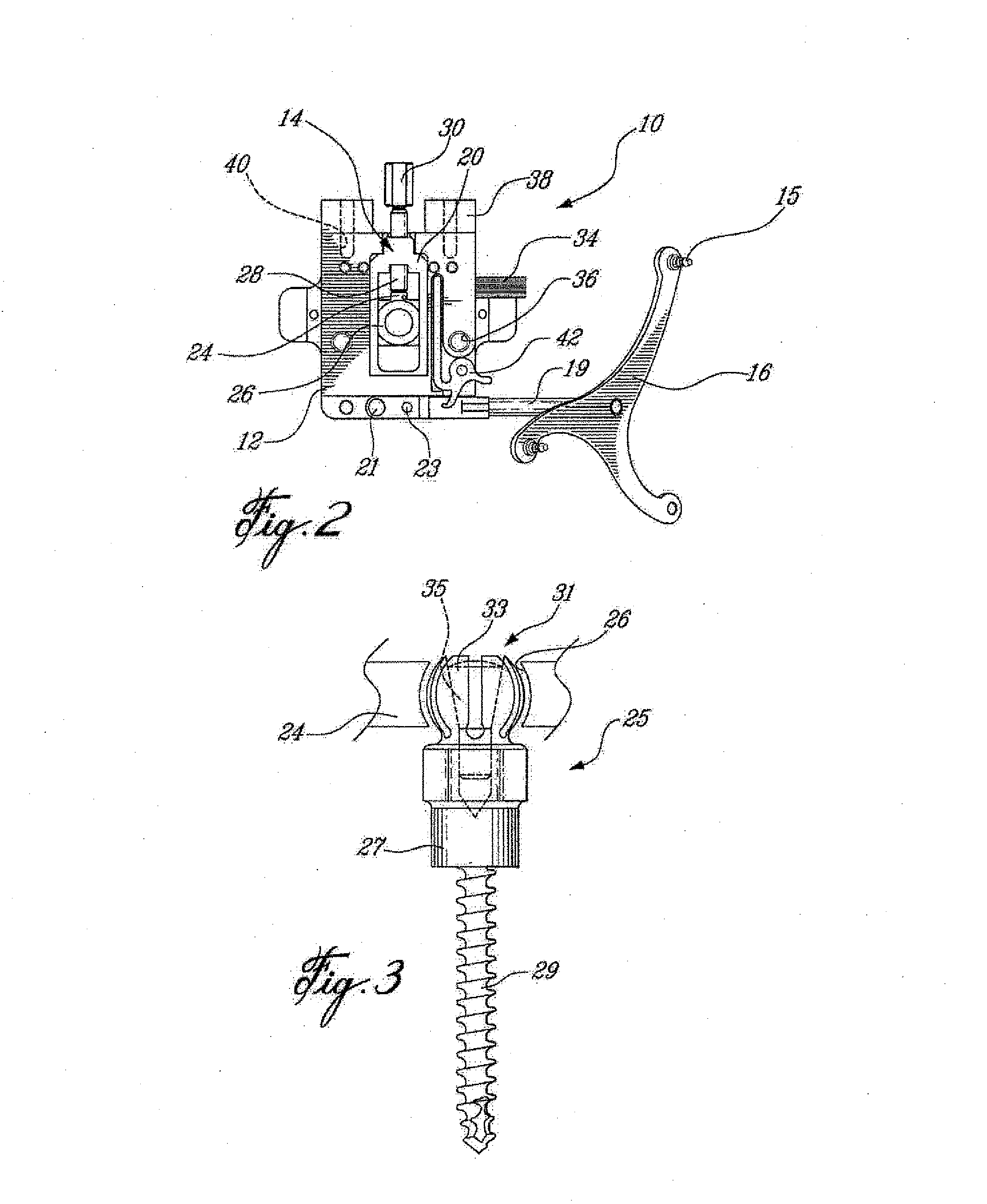
[0053] Throughout this application, the preferred embodiment of the present invention will be referred to as a universal positioning block or simply positioning block, and is preferably for use in total knee replacement surgery and is adapted to accurately position and align a cutting tool. The universal positioning block comprises a guide body or cutting tool guide element that is operatively engageable with a cutting tool, whether directly by providing a cutting guide surface on the cutting tool guide element itself or by being engageabie with a separate cutting guide block which is used to guide the cutting tool. It is to be understood that such a cutting tool as defined herein includes all instruments which can remove bone from a bone element, such as drills and saws for example, and that such a cutting tool guide element or surface thereon is similarly adapted for guiding any instrument which can remove bone from a bone element such as a drill bit or a saw blade.

[0054] Prefera...


PUM


Abstract

A positioning block (10) for use in total knee replacement surgery, permitting five degrees-of-freedom movement relative to a bone element (39) to which it is fixed. The positioning block (10) comprises a rotational mounting element (14) that is removably engaged to the bone element such that the mounting element (14) is selectively rotatable relative to the bone element, about three substantially perpendicular axes of rotation. A guide body portion (12) is engaged with the mounting element (14) such that it is translatable relative thereto along a proximal-distal axis (43) and an anterior-posterior axis (47), while being rotationally fixed relative to the mounting element (14) such that the guide body portion (12) and the mounting element (14) rotate together relative to the bone element (39).

Description

CROSS-REFERENCE TO RELATED APPLICATIONS [0001] This a divisional application of U.S. patent application Ser. No. 11 / 062,737 filed Feb. 23, 2005, which is a continuation of International Patent Application Serial No. PCT / CA03 / 01307 filed Aug. 25, 2003, which claims priority on: U.S. Provisional Application No. 60 / 405,353, filed on Aug. 23, 2002; U.S. Provisional Application No. 60 / 405,326, filed on Aug. 23, 2002; and U.S. application Ser. No. 10 / 357,493, filed on Feb. 4, 2003; the entire contents of each of these patent applications is incorporated herein by reference.FIELD OF THE INVENTION [0002] The present invention relates generally to a surgical tool for use in knee surgery. More particularly, the present invention is directed to a multiple degree-of-freedom positioning reference block and a surgical tool guide, for use in computer assisted surgery (CAS) total knee replacement. BACKGROUND OF THE INVENTION [0003] Accuracy of cuts and drilled holes is important in knee arthroplast...

Claims


Application Information

Patent Timeline
Patent Type & Authority Applications(United States)
IPC IPC(8): A61F5/00
CPCA61B17/154A61B17/155A61B17/157A61B17/1703A61B17/1725A61B17/1764A61B2019/5483A61B19/50A61B19/5244A61B2017/00725A61B2019/5255A61B2019/5416A61B19/201A61B34/10A61B34/20A61B90/11A61B2034/2055A61B2090/3916A61B2090/3983
Inventor COUTURE, PIERREPELLETIER, BENOLTRICHARD, ALAINABIVEN, JEAN-GUILLAUMEGARCEAU, PATRICK
Owner ORTHOSOFT ULC
Why Eureka
Try Eureka