Electrically conductive fabric jumpers

Inactive Publication Date: 2008-03-20
BERNARDINI ALLEN J
View PDF3 Cites 15 Cited by
  • Summary
  • Abstract
  • Description
  • Claims
  • Application Information

AI Technical Summary

Problems solved by technology

While functional, this process is expensive, time consuming to do, and the wires are difficult to terminate except by hard wiring or with electrical connectors which are bulky, fragile and non washable or not dryable in machines.
This is a detriment to mass production and increases the cost and manufacturing time of the garment.
It would be very advantageous to be able to cut and sew the fabrics having electrically conductive yarns like other garments but the c

Method used


Image

  • Electrically conductive fabric jumpers
  • Electrically conductive fabric jumpers
  • Electrically conductive fabric jumpers

Examples


Embodiment Construction

[0026]There exists in the prior art, a process called “heat staking”. This requires a special machine, which applies heat and pressure at the same time to bond two pieces of material together. The materials can be dissimilar.

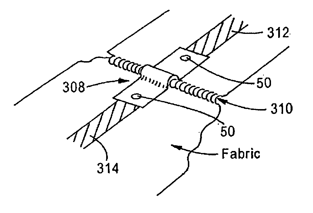
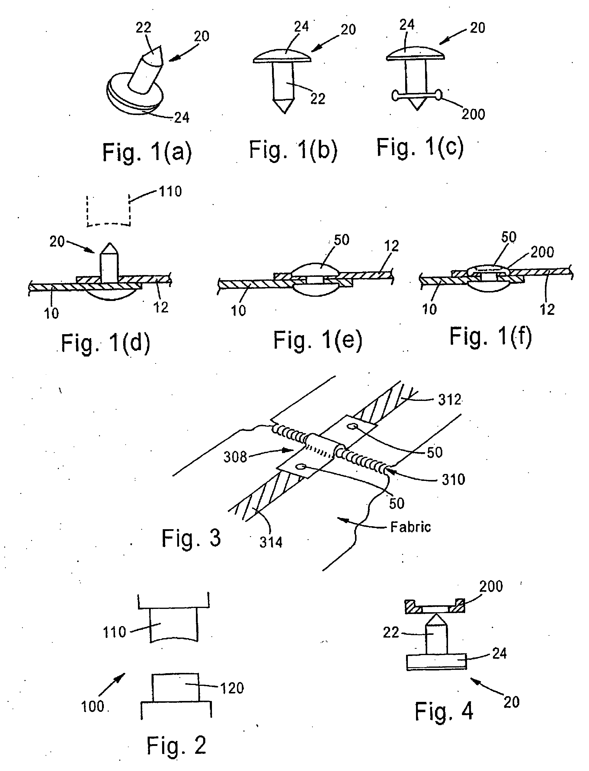
[0027]The present invention utilizes the heat staking process in a configuration to join two conductive yarn traces 10, 12 (see FIGS. 1(a)-(f)) or pads by piercing them with a thermo plastic stud 20 (FIGS. 1(a)-(c)) shaped somewhat like a rivet with a pointed post 22 to pierce the fabrics 10, 12 (FIG. 1). Although the post 22 is shown as pointed, it can be any desired shape. The stud 20 also has a cylindrical post 22 and a head 24. Although shown with a cylindrical post 22 and round head 24, these heads and posts can be any shape that can be “heat staked”. The stud 20 can have one or more posts 22 (FIG. 4). One post 22 is shown for simplicity. A properly designed tool 100 (FIG. 2 shows a typical tool) will then be lowered to meet the pointed tip and using the pr...


PUM

PropertyMeasurementUnit
Mechanical strengthaaaaaaaaaa
Electrical conductivityaaaaaaaaaa
Electrical conductoraaaaaaaaaa

Abstract

Disclosed is a heat staking process using a configuration to join two conductive yarn traces or pads by piercing them with a thermo plastic stud shaped somewhat like a rivet with a pointed post to pierce the fabrics. A properly designed tool can be lowered to meet the pointed tip of the stud and by using the proper heat and proper compression will join the two fabric pieces mechanically and electrically. The heat and compression formed stud 50 will provide mechanical strength and actually seal the connection if so required.

Description

RELATED APPLICATION[0001]The present application is based on, and claims priority from, U.S. Application No. 60 / 825,996, filed Sep. 18, 2006, the disclosure of which is hereby incorporated by reference herein in its entirety.FIELD OF THE INVENTION[0002]The present invention is directed to the field of electrical connectors, and more specifically, the field of electrical connectors to connect across conductive fabric sections. Even more specifically, the present invention is directed to jumpers from one conductive fabric section to another in order to complete an electrical circuit across seams, patches, hems and the like.BACKGROUND OF THE INVENTION[0003]It is recognized in the art that there is a need for electrical connections—in specific—jumpers from one conductive fabric section to another in order to complete an electrical circuit across seams, patches, hems and the like. There is also a need to terminate two or more electrically conductive yarns or traces to complete a circuit....

Claims


Application Information

Patent Timeline
IPC IPC(8): H01R43/02H01B1/00
CPCH01B1/124H01R4/06Y10T29/4921Y10T29/49222H01R43/00
Inventor BERNARDINI, ALLEN J.
Owner BERNARDINI ALLEN J
Why Eureka
Try Eureka