Optical information detecting method, optical head, and optical disc apparatus

a technology of optical discs and information detecting methods, applied in the field of optical information detecting methods, optical head, optical disc apparatus, can solve the problems of difficult application of disclosed techniques for practical purposes, unsuitable for reducing the size of optical systems, etc., and achieves small reflected signals, low reflectivity, and increase the s/n ratio

Inactive Publication Date: 2008-03-20
HITACHI CONSUMER ELECTRONICS CORP
View PDF3 Cites 29 Cited by
  • Summary
  • Abstract
  • Description
  • Claims
  • Application Information

AI Technical Summary

Benefits of technology

[0034] Thus, since the reference light and the signal light reflected by the disc can be composed on the first, second, third, and fourth detectors and amplified by an interference effect for reproduction, a very small reflected signal can be detected with a high S / N. Namely, it becomes possible to significantly increase the S / N ratio in, particularly, a multilayer medium having low reflectivity and small signal amount, or during high-speed reproduction in which the influence of wideband noise is large.
[0035] In accordance with the present invention, no adjustment of the difference in the optical paths of two light beams is required in principle. Thus, an optical disc apparatus having a high signal amplification effect and comprising an interference-type optical disc signal detection system suitable for reduction of the size of the optical system can be provided inexpensively. Furthermore, a reproduction signal that is stable at all times and amplified with high quality can be obtained even when there is an optical path length variation due to the disc undulation and the like.

Problems solved by technology

The optical systems of the interferometers used in the aforementioned conventional art are all of the Mach-Zehnder type, which comprise a large number of optical components and are not suitable for reduction of the size of the optical system.
Another problem is that the publications do not provide any method of adjusting the optical path difference of the two light beams, thus making the disclosed techniques difficult to apply for practical purposes.

Method used


Image

  • Optical information detecting method, optical head, and optical disc apparatus
  • Optical information detecting method, optical head, and optical disc apparatus
  • Optical information detecting method, optical head, and optical disc apparatus

Examples


embodiment 1

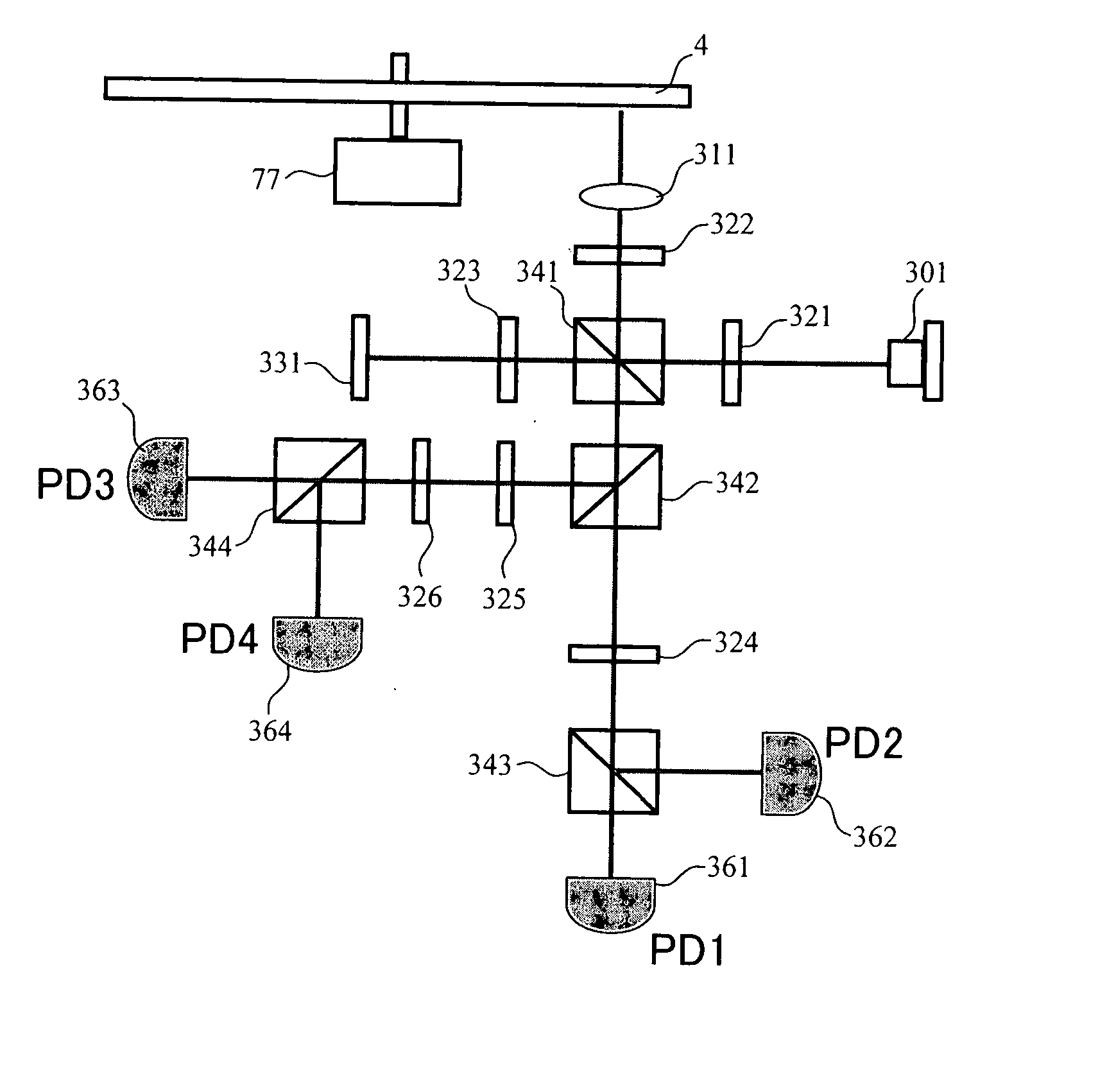
[0048]FIG. 1 shows a block diagram of an optical system for realizing an optical signal detecting method of the present invention. Light emitted by a laser 301 passes through a first λ / 2 plate 321 whereby the polarization direction of the light is rotated by 45°. The light with the rotated polarization is separated by a first polarizing beam splitter 341 into two beams of linearly polarized light that are perpendicular to each other. The light with one polarization (detection light) is reflected and passes through a first λ / 4 plate 322, by which the light is converted into circularly polarized light, which is focused by an objective lens 311 and shone onto an optical disc 4. Reflected light (to be hereafter referred to as a signal light) from the optical disc 4 as it is rotated by a spindle motor 77, is returned back to parallel light by the objective lens 311 and then back to linearly polarized light via the first λ / 4 plate 322. The direction of this linearly polarized light is per...

embodiment 2

[0057] While in Embodiment 1 signal light and reference light were assumed to be completely coherent, the resonator length of conventional semiconductor lasers is short and their optical coherence length is not very long. FIGS. 8A to 8C show the change in reproduction signal intensity in a case where, in the configuration of Embodiment 1, a conventional blue-light semiconductor laser (LD) was employed. In order to track the disc as it undulates, the objective lens 311 is moved up and down, resulting in changes in the optical path length of the signal light. However, since the optical path length of reference light does not change, an optical path length difference is created between reference light and signal light. If such optical path length difference becomes greater than the coherence length of LD, the output of Equation (7) cannot be obtained. Generally, the output in an incompletely coherent state is Equation (7) times coherency. Coherency is 1, i.e., 100%, in a completely coh...

embodiment 3

[0060] While in Embodiments 1 and 2 a reproduction signal was obtained by the operation according to Equation (7), it is also possible to obtain a reproduction signal without performing the square-root operation.

[0061] Namely, (Sig1)2+(Sig2)2=|Esig|2·|Eref|2 is used as the signal. Such operation does not require the square-root operation, so that the circuit configuration can be simplified and the energy of signal light becomes proportional to reproduction output. Since the reproduction signal output is also proportional to |Esig|2 in the conventional optical signal detection method, the method of the present embodiment has the advantage that it can employ the same conventional signal processing method.


PUM


Abstract

In multilayer optical discs and high-speed optical discs, the amount of reproduction light per unit time greatly decreases and the reproduction signal quality (S/N) significantly drops due to the low effective reflectivity and the short read time of the medium. These problems are solved by causing reflected signal light from the optical disc and reference light, which is separated from the same light source and introduced into a detector without being shone onto the optical disc, to interference with each other on the detector. Detector outputs having four different interference states are simultaneously obtained, the interference states being displaced at intervals of 90° in terms of the phase relationship between the reference light and the signal. Based on a operation of the four detector outputs, a reproduction signal can be obtained that is stable at all times and amplified with high quality, even when there is an optical path length variation due to disc undulations.

Description

CLAIM OF PRIORITY [0001] The present application claims priority from Japanese application JP2006-245848 filed on Sep. 11, 2006, the content of which is hereby incorporated by reference into this application. BACKGROUND OF THE INVENTION [0002] 1. Field of the Invention [0003] The present invention relates to an improvement of the signal-to-noise ratio of a reproduction signal from an optical disc apparatus. [0004] 2. Background Art [0005] With the commercialization of Blu-ray Disc (BD) that employs blue semiconductor laser and a high-NA objective lens, the optical disc has virtually reached a limit in terms of optical system resolution, and for further increase in capacity, increasing the number of layers is believed to offer a major solution. In a multilayer optical disc, given the need to have substantially equal amounts of light detected from each layer, the reflectivity of certain layers inevitably needs to be reduced. However, in addition to the increases in the capacity of opt...

Claims


Application Information

Patent Timeline
Patent Type & Authority Applications(United States)
IPC IPC(8): G02B27/40
CPCG11B7/005G11B2007/0013G11B7/1356G11B7/13
Inventor MIYAMOTO, HARUKAZUMIKAMI, HIDEHARUSHIMANO, TAKESHI
Owner HITACHI CONSUMER ELECTRONICS CORP
Why Eureka
Try Eureka