Eureka AIR delivers breakthrough ideas for toughest innovation challenges, trusted by R&D personnel around the world.

Severe application off-highway truck body

Inactive Publication Date: 2008-03-20
HAGENBUCH LEROY G
View PDF81 Cites 25 Cited by
  • Summary
  • Abstract
  • Description
  • Claims
  • Application Information

AI Technical Summary

Benefits of technology

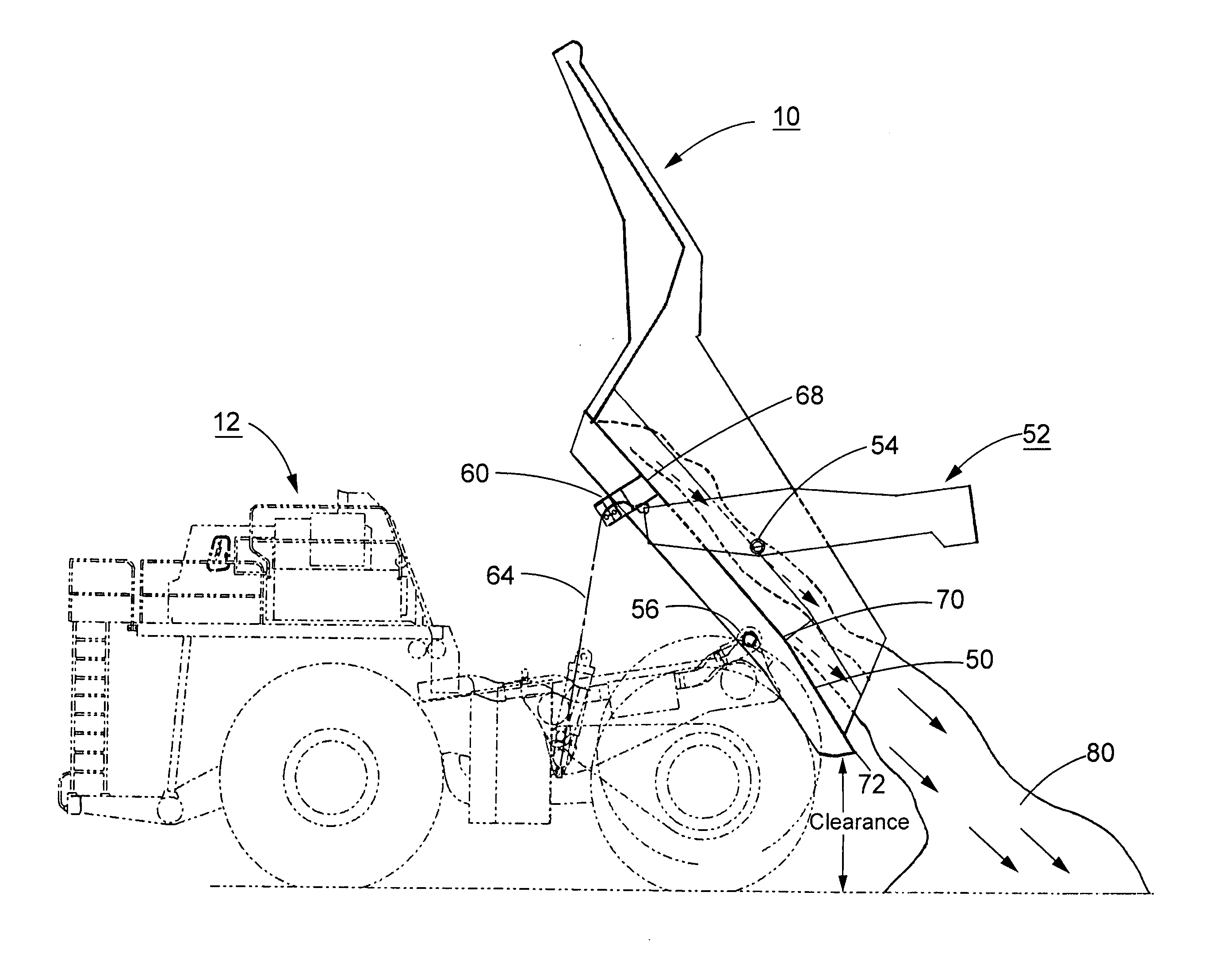
[0009]A body for handling highly abrasive material is designed to minimize the wear on the rearward area of the body during the dumping of a load from the body. The floor length of the body's extension rearward is truncated and lowered with respect to conventional bodies that use the length of the body's floor to inhibit material spillage. But, the body floor length can only be shortened and lowered if the body still hauls the amount of material required to reach the rated payload of the truck chassis and material spillage is minimized. Instead of relying on the length of the floor for controlling material spillage, the body incorporates a tailgate. With the addition of a tailgate to the rear of the body, the body floor can be shortened and lowered and the rated payload can still be carried. Those skilled in the art of designing dump bodies for large, off-highway trucks will appreciate that the addition of a tailgate to a body intended for hauling dense material, which is what abrasive material often is, is contrary to conventional practice. In the invention, however, the tailgate cooperates with other aspects of the invention to provide a dump body that hauls and dumps abrasive material with less wear than that experienced by conventional dump bodies without tailgates.
[0010]To reduce the wear on the floor at the rearward portion of the body, the floor is angled downwardly with respect to the angle of the forward area of the floor. By angling the floor downwardly at its rearward portion, the frictional force of the abrasive material as it flows from the body during the dumping of a load is lessened. In a body whose rear portion of the floor is tipped downwardly with respect to the front of the floor, material flows from the body and over a point where the floor breaks away from one plane to another. As the material flows out the rear of the body, the trajectory of the material is influenced by the inclination of the forward part of the body where the forward floor section has a different angle than the rearward portion of the floor. The trajectory of the material tends to cause the material to overshoot the rearward area of the shortened floor and free fall, thereby reducing abrasion to that area of the floor. Moreover, the increased downward inclination of the rear floor section encourages the material as it flows from the body to tumble instead of sliding, which further decreases the abrasive wear on the floor.
[0011]Additionally, by shortening the body's floor, at full tilt of the body, the ground clearance of the rear of the body to ground is substantially increased. By increasing the ground clearance, there is less damage to the rear body edge from dumping the body into material already on the ground. Furthermore, where material is being dumped over an embankment, some areas require by regulation that a “dump berm” is at least as high as half the height of the largest tire operating in the haulage vehicle fleet in order to avoid accidentally backing the truck over the embankment. With conventional “V-shaped” or “duck tailed” bodies, this safety “dump berm” is continually being dumped into, destroying the dump berm and requiring it to be continually maintained with a piece of dozing equipment. With a body whose floor length is shortened, the dumping of the rear of the body into the safety dump berm is either stopped or minimized.
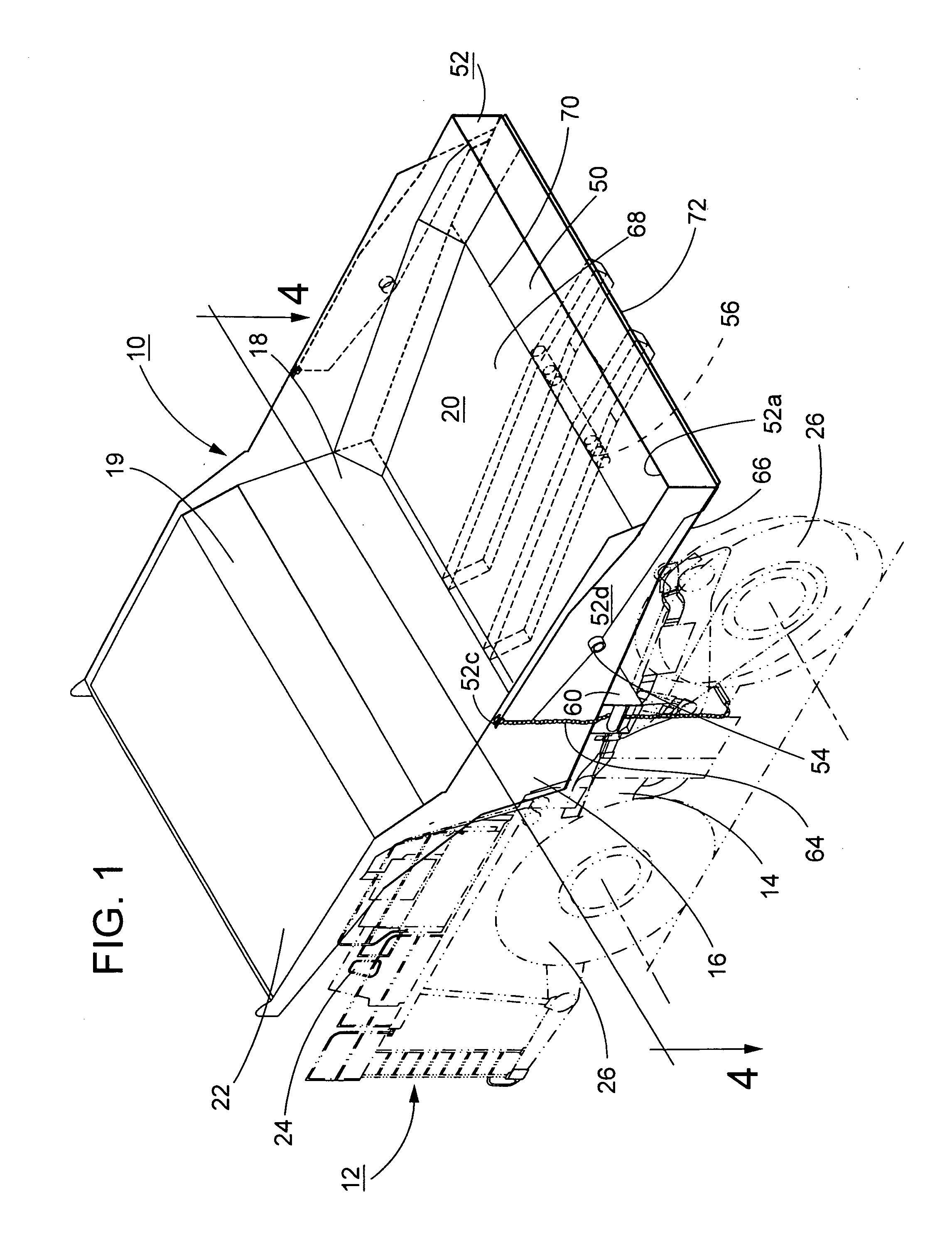
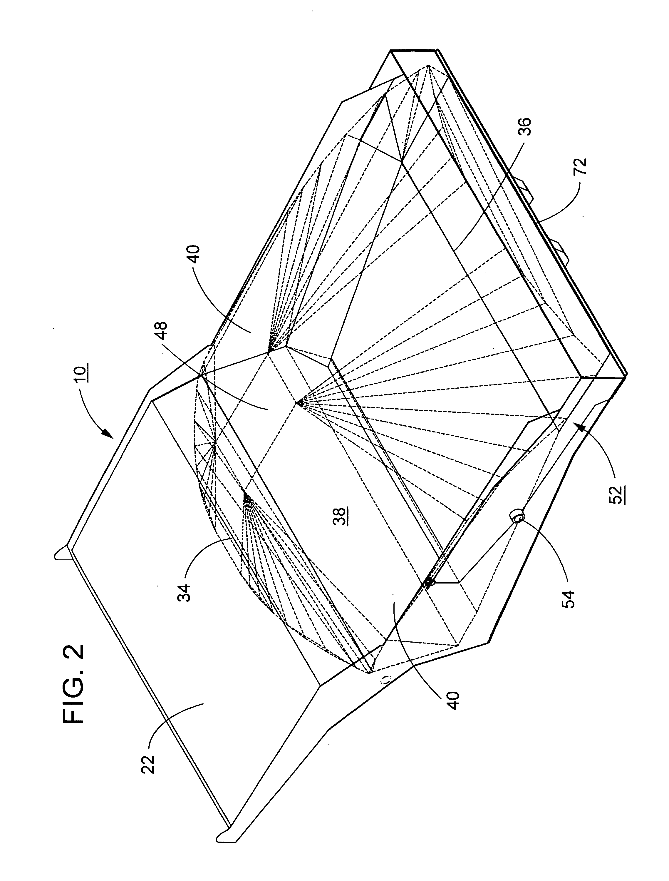
[0012]To still further reduce the wear of the body from hauling and dumping abrasive material, the sidewalls of the body are flared outwardly from the front to the rear of the body. The flared sidewalls provide an opportunity for the material to flow laterally as it is dumped, which relieves the amount of friction experienced by the sidewalls. With the sides and bottom of the load not fully supported as the material flows from the dump body, the load tends to disintegrate as it flows from the body (e.g., distributes more evenly and breaks up in free fall), particularly for cohesive materials that otherwise may tend to remain as a monolithic mass as they are dumped.
[0013]Hauling material that is extremely cohesive, such as the oil sands of Northern Alberta, Canada is an example of a severe haulage application for which the body of the invention is particularly appropriate. These oil sands when hauled and dumped from a truck body typically tend to dump as a single homogeneous mass, or glob, commonly referred to in the industry as a “loaf.” A haulage vehicle incorporating the dump body of the invention has a floor that drops away and body sidewalls that outwardly taper away from the trajectory of the loaf as it is being dumped from the body, which encourages the unsupported material to free fall and break up as it moves out of the body. Though cohesive, the loaf will separate and tend to tumble and flow in smaller granulations of the material rather than dumping from the body as a substantially single mass that grinds against the rear floor area and sidewalls of the dump body. In contrast, conventional bodies tend to underpin the loaf being dumped over the full length of the truck body, encouraging the cohesive material to exit the dump body as a homogeneous mass.

Problems solved by technology

But, the body floor length can only be shortened and lowered if the body still hauls the amount of material required to reach the rated payload of the truck chassis and material spillage is minimized.
Moreover, the increased downward inclination of the rear floor section encourages the material as it flows from the body to tumble instead of sliding, which further decreases the abrasive wear on the floor.
With conventional “V-shaped” or “duck tailed” bodies, this safety “dump berm” is continually being dumped into, destroying the dump berm and requiring it to be continually maintained with a piece of dozing equipment.

Method used


Image

  • Severe application off-highway truck body
  • Severe application off-highway truck body
  • Severe application off-highway truck body

Examples


Embodiment Construction

[0022]Referring now more particularly to the drawings there is shown in FIGS. 1-5 a dump body 10 for a heavy-duty off-highway truck 12 whose general design is in keeping with the three-dimensional modeling of a load for the body and the dimensioning of the body to accommodate that load as described in co-pending U.S. patent application Ser. No. 09 / 593,647, filed Jun. 13, 2000 and U.S. patent application Ser. No. 09 / 333,379, filed Jun. 15, 1999. Both of these applications have been incorporated by reference into this application for everything they describe.

[0023]The truck 12 includes a chassis 14 to which the dump body 10 is attached for pivotal movement about an axis 56 between a lowered position for receiving and transporting a load of material (FIGS. 1 and 3) and a raised position for dumping a load of material (FIG. 5). As shown in FIG. 1, the dump body 10 is generally constructed of steel panels that define the shape of the dump body and beams that form the structural framework...


PUM


Abstract

An open top body of an off-highway haulage vehicle is described for severe hauling applications such as hauling of high density, abrasive material. The body has a floor divided into at least two sections with first and second sections angled at different inclinations. The second section extends to the rear edge of the floor and is at an angle of inclination greater than the first section. The opposing sidewalls of the body extend vertically from the floor are flared or taper along their length such that the body floor is wider at the rear of the body than it is at the front. The body includes a tailgate pivotally attached to the sidewalls for rotation between closed and opened positions in response to the bumping of the load by the body.

Description

CROSS-REFERENCE TO RELATED APPLICATIONS[0001]This patent application is related to co-pending U.S. patent application Ser. No. 09 / 593,647, filed Jun. 13, 2000, Ser. No. 09 / 333,379, filed Jun. 15, 1999, Ser. No. 10 / 286,095, filed Nov. 1, 2002 and Ser. No. 10 / 374,803, filed Feb. 25, 2003, each of which is incorporated by reference in its entirety for everything it describes.BACKGROUND OF THE INVENTION[0002]In mining and construction environments, heavy-duty off-highway trucks are used to haul a variety of materials such as, for example, coal, rock, ore, overburden materials. Some environments expose the trucks to severe hauling conditions in which the material being hauled is relatively dense (e.g., 2700+ lbs. / cubic yard) such as heavy metal ores (e.g., iron, gold and copper ore) and oil sands such as those mined in northern Canada. These types of materials can be extremely abrasive and cause severe wear on the inside of the bodies, particularly the floor area and particularly on the ...

Claims


Application Information

Patent Timeline
IPC IPC(8): B60P1/28
CPCB60P1/286
Inventor HAGENBUCH, LEROY G.
Owner HAGENBUCH LEROY G
Why Eureka
Eureka Blog
Learn More