Sensor for measuring relative conductivity changes in biological tissue

a technology of relative conductivity and biological tissue, which is applied in the field of electromagnetically impedance sensor, can solve the problems of long-term chronic use of current electromagnetic impedance system, in which electrodes are placed on the patient's chest, may be impractical, and inherently lack the level of precision that may be useful, and achieve the effect of reducing the parasitic capacitance between turns

Inactive Publication Date: 2008-03-20
INFORMATION SYST LAB
View PDF16 Cites 6 Cited by
  • Summary
  • Abstract
  • Description
  • Claims
  • Application Information

AI Technical Summary

Benefits of technology

[0008]Structurally, both antennas consist of flat wire and are preferably printed circuit board antennas. Further, the flat wire of the transmit antenna is formed with three turns while the flat wire of the receive antenna is formed with six turn

Problems solved by technology

In any case, the long-term chronic use of current electromagnetic impedance systems, in which electrodes are plac

Method used


Image

  • Sensor for measuring relative conductivity changes in biological tissue
  • Sensor for measuring relative conductivity changes in biological tissue
  • Sensor for measuring relative conductivity changes in biological tissue

Examples


Embodiment Construction

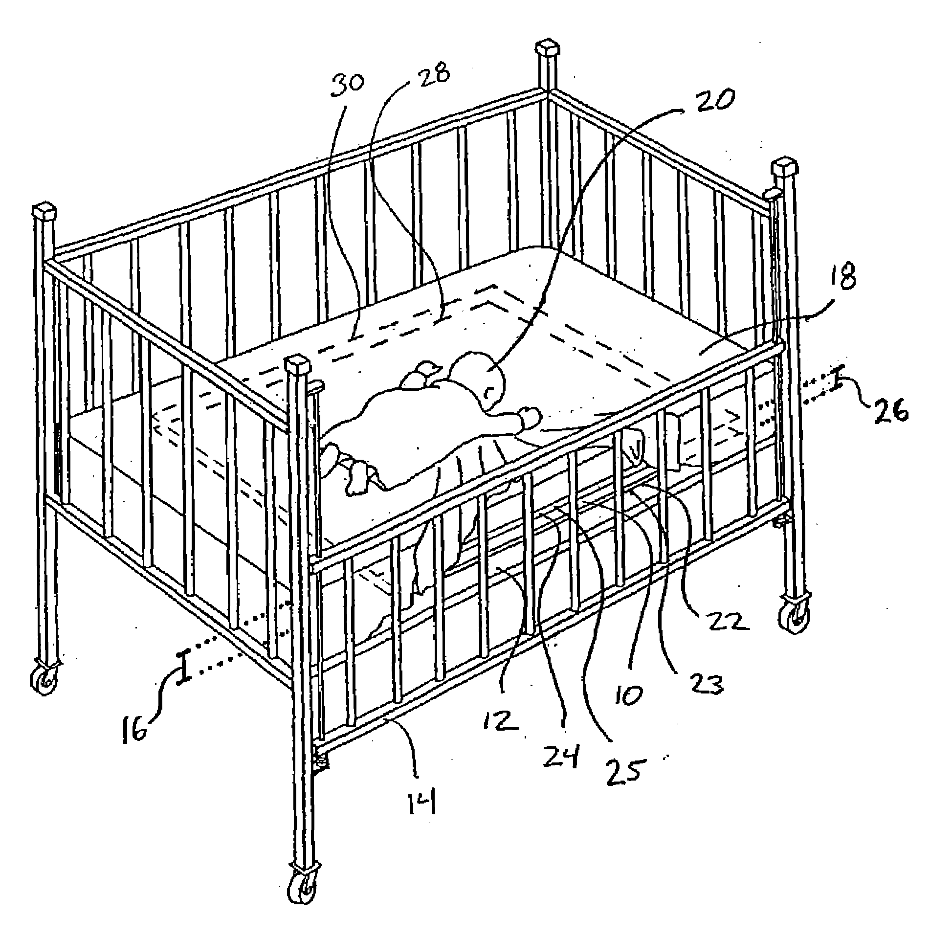
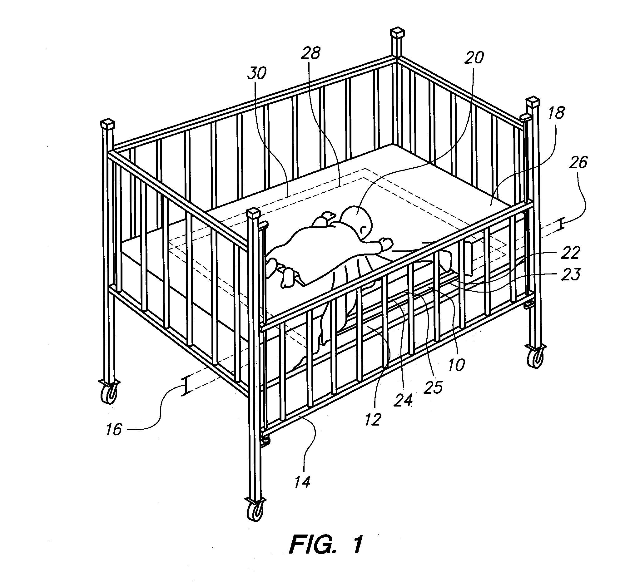
[0018]Referring initially to FIG. 1, a sensor for detecting changes in electrical conductivity in an environment is shown and designated 10. For exemplary purposes, the sensor 10 is mounted within a mattress 12 in a crib 14 at a predetermined distance 16 from the surface 18 of the mattress 12. Further, it can be seen that an infant 20 is sleeping on the surface 18 of the mattress 12. As shown, the sensor 10 includes a transmit antenna 22 mounted on a board 23 and a receive antenna 24 mounted on a board 25. The antennas 22, 24 are separated by a selected distance 26. Specifically, the antenna 22 defines a plane 28, and the antenna 24 defines a substantially parallel plane 30 at the selected distance 26 from the plane 28. For purposes of the present invention, the antenna 22 transmits a signal that is received by the antenna 24. Thereafter, the received signal is monitored and electromagnetic impendence detection is used to detect changes in the electrical conductivity of the environm...


PUM


Abstract

A sensor for detecting changes in electrical conductivity in a patient is disclosed. The sensor includes a transmit antenna that has an interior area bounded by a periphery. Importantly, the periphery includes an outer ring portion and an inner ring portion therein that partially surrounds an open area. Further, the sensor includes a receive antenna that has a substantially circular circumference that bounds an interior area. In order to balance the antennas, approximately half of the interior area of the receive antenna is superposed on the interior area of the second antenna. In operation, the antennas are positioned at a selected distance from one another near a patient. Then a signal is sent from the transmit antenna to the receive antenna. The signal is affected by the conductivity of the patient. As a result, the received signal may be monitored to detect electrical conductivity changes in the patient.

Description

FIELD OF THE INVENTION[0001]The present invention pertains generally to an electromagnetic impedance sensor. More particularly, the present invention pertains to a sensor that monitors a patient's respiratory and heart rate by detecting changes in electrical conductivity. The present invention is particularly, but not exclusively, useful as a sensor for detecting an onset of respiratory distress in a patient.BACKGROUND OF THE INVENTION[0002]Mammals' bodies are comprised mainly of water with an average conductivity and relative dielectric constant that is approximately that of seawater. Further, these parameters vary significantly for each of the body's organs. As a result of this variance, movement or deformation of the shape of a body results in changes in the electrical conductivity of the body. For instance, the change in shape of a body during respiration causes a measurable change in electrical conductivity. Further, during the cardiac cycle, the volume of blood in each chamber...

Claims


Application Information

Patent Timeline
IPC IPC(8): G08B23/00A61B5/00G08B1/08
CPCA61B5/053A61B2560/0242A61B5/6887A61B5/0809
Inventor WATSON, BRIANRIDGWAY, JEFFREYCASTELAZ, PATRICK
Owner INFORMATION SYST LAB
Why Eureka
Try Eureka