Amplifier failure detection apparatus

a technology for failure detection and amplifiers, applied in amplifiers with semiconductor devices/discharge tubes, amplifier details, instruments, etc., can solve the problems of alarm output, cost and size disadvantages of apparatus, poor communication quality in those channels, etc., and achieve accurate detection of power amplifier failures.

Inactive Publication Date: 2008-03-20
FUJITSU LTD
View PDF7 Cites 19 Cited by
  • Summary
  • Abstract
  • Description
  • Claims
  • Application Information

AI Technical Summary

Benefits of technology

[0027]Taking into consideration the aforementioned problems, it is the object of the present invention to accurately detect failure of a power amplifier even when the gain of the amplifier changes in accordance with the input-amplitude level.

Problems solved by technology

This power leakage becomes noise in other channels, which causes the quality of communication in those channels to become poor.
However, in order to increase the linear range, an amplifier having performance which is greater than that actually required becomes necessary, and thus there is a problem in that cost and size of the apparatus become a disadvantage.
Conventionally, since the gain was constant, there was no problem even though the threshold value of the gain-fluctuation alarm was set to a constant value, however, in the case of a power amplifier whose gain is not constant, even though the amplifier may be operating properly, there is a problem in that the gain-monitor voltage Vout drops as shown in FIG. 17 and becomes lower than the threshold value VAL of the gain-fluctuation alarm, and thus an alarm is output by mistake.
Therefore, in these cases, when the alarm-threshold voltage VAL that follows the fluctuation in the gain-monitor voltage is not set, there is a problem in that it is not possible to correctly detect amplifier failure.
However, this prior art does not detect failure of the power amplifier.
When there are changes in the gain characteristics with respect to the input-amplitude level, there is no prior art that accurately detects failure of a power amplifier.

Method used


Image

  • Amplifier failure detection apparatus
  • Amplifier failure detection apparatus
  • Amplifier failure detection apparatus

Examples


embodiment 1

(A) Embodiment 1

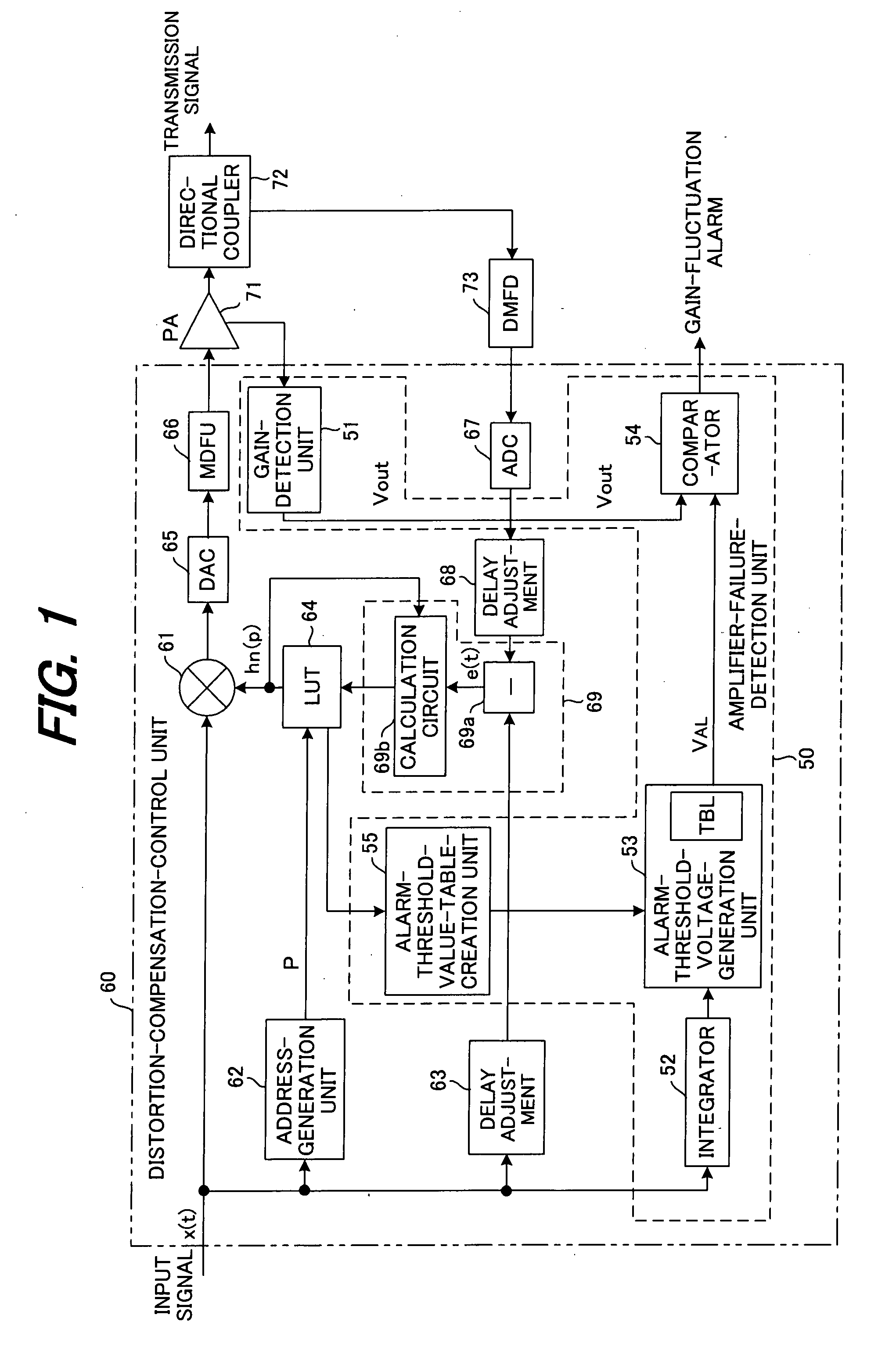
[0061]FIG. 1 is a drawing showing the construction of a transmission apparatus in the radio transmitter of the present invention. Except for an amplifier failure detection unit 50, this transmission apparatus comprises the same functions as a prior transmission apparatus with a power amplifier distortion compensation function.

[0062]A transmission signal x(t) is respectively input to a predistortion unit 61, address-generation unit 62 and delay unit 63 of a distortion-compensation-control unit 60. The address-generation unit 62 computes the power p (=|x(t)|2) of the transmission signal x(t) and outputs that power p as a read address in the distortion-compensation-coefficient-memory unit (look-up table LUT) 64, then the look-up table LUT 64 reads the distortion-compensation coefficient hn(p) from that address and inputs it to the predistortion unit 61. The predistortion unit 61 multiplies the transmission signal x(t) by the distortion-compensation coefficient hn(p), th...

embodiment 2

(B) Embodiment 2

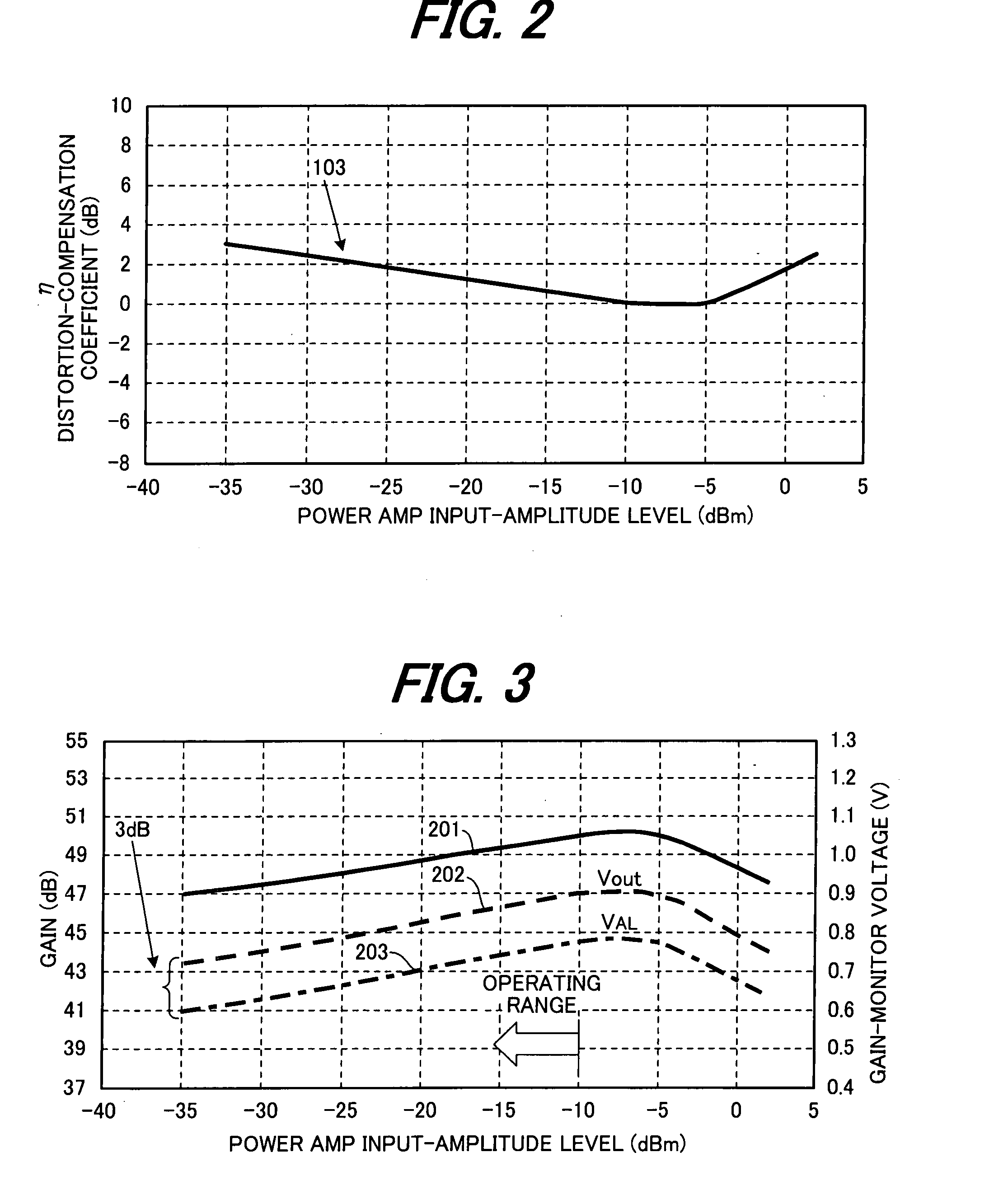
[0088]FIG. 5 is a drawing explaining a second embodiment of the present invention. In the first embodiment, an alarm-threshold voltage that corresponded to the input-amplitude level was calculated based on the input-amplitude level vs. gain characteristics 201 (see FIG. 3) of the power amplifier and saved in a table TBL. In other words, in the first embodiment, the alarm-threshold voltage characteristics 203 that are shown in FIG. 3 were saved in a table TBL. However, in this second embodiment, as shown in FIG. 5, the range of the input-amplitude level in which an alarm is output is divided into a plurality of divisions (two divisions in the figure), and alarm-detection levels VAL1, VAL2 for each division correspond to a respective input-amplitude level and are stored sequentially in a table TBL, and an alarm-threshold voltage is generated that corresponds to the respective input-amplitude level.

[0089]The transmission apparatus in the radio transmitter of this second...


PUM


Abstract

An amplifier failure detection apparatus for a radio transmitter that has a function for compensating for amplifier distortion of the radio transmitter and a function for determining amplifier failure has occurred by detecting that the gain of an amplifier has dropped a set level or more, in which: a gain-detection unit detects the gain of the amplifier; an alarm-detection-level-generation unit, which has a table for storing alarm-detection levels that correspond to input-amplitude levels, generates an alarm-detection level that corresponds to an input-amplitude level; and a comparison unit compares the gain detected by the gain-detection unit with the alarm-detection level, and generates an alarm based on the comparison results.

Description

BACKGROUND OF THE INVENTION[0001]This invention relates to an amplifier failure detection apparatus, and more particularly to an amplifier failure detection apparatus of a radio transmitter that comprises a function for correcting distortion of the amplifier of the radio transmitter, and detects the gain of the amplifier drops a set level or more in order to determine that amplifier failure has occurred.[0002]Recently, high-performance transmission through digitization is often used in radio transmission. When multi value phase modulation is used in radio transmission, techniques for linearizing the amplification characteristics of a power amplifier, suppressing non-linear distortion, and reducing the power leakage to adjacent channels is particularly important; also when using an amplifier having poor linearity to improve power efficiency, it is essential that a technique be used to compensate for the resulting distortion.[0003]FIG. 9 is a block diagram showing an example of a tran...

Claims


Application Information

Patent Timeline
Patent Type & Authority Applications(United States)
IPC IPC(8): G08B21/00
CPCH03F1/3247H04B2001/0416H04B1/0466H03F2201/3233
Inventor MAEDA, HIROAKIONO, TAKASHIOKAZAKI, YOUSUKEHONDA, HIROTAKEEZUKA, HIROYUKI
Owner FUJITSU LTD
Why Eureka
Try Eureka