Transmission circuit and communication device

a transmission circuit and communication device technology, applied in the field of transmission circuits, can solve the problems of deteriorating transmission signal quality, increasing power consumption and size of transmission circuits, and increasing circuit size, and achieves the effects of high linearity, small size, and high efficiency

Active Publication Date: 2008-03-20
INTERDIGITAL PATENT HLDG INC
View PDF4 Cites 30 Cited by
  • Summary
  • Abstract
  • Description
  • Claims
  • Application Information

AI Technical Summary

Benefits of technology

[0018]Therefore, an object of the present invention is to provide a transmission circuit for solving the above problem, which is small in size, operates with high efficiency and outputs a transmission signal having high linearity, and also to provide a communication device using the transmission circuit.

Problems solved by technology

This consequently causes an increase in power consumption and size of the transmission circuit.
Thus, the conventional transmission circuit 700 has a problem of decreased power efficiency and increased circuit size.
Also, there is a possibility that a quality of the transmission signal deteriorates due to the quantization noise which has not been removed by the band-pass filter 75.
This consequently causes an increase in power consumption and size of the transmission circuit.
Thus, the conventional transmission circuit 800 has a problem of decreased power efficiency and increased circuit size.
Also, there is a possibility that a quality of the transmission signal deteriorates due to the quantization noise which has not been removed by the band-pass filter 84.
This consequently causes an increase in power consumption and size of the transmission circuit.
Thus, the conventional transmission circuit 900 has a problem of decreased power efficiency and increased circuit size.
Also, there is a possibility that a quality of the transmission signal deteriorates due to the quantization noise which has not been removed by the band-pass filter 95.

Method used


Image

  • Transmission circuit and communication device
  • Transmission circuit and communication device
  • Transmission circuit and communication device

Examples


first embodiment

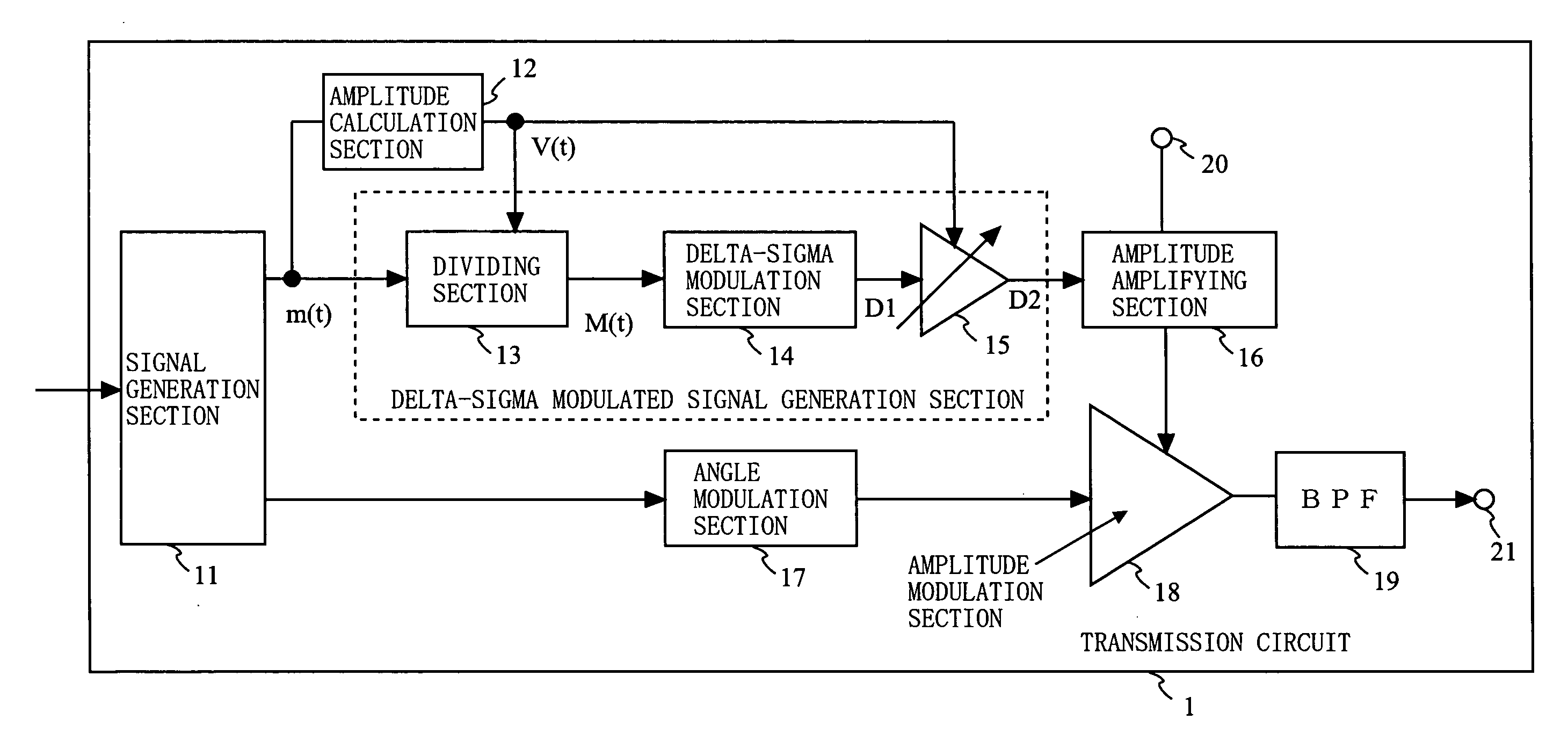
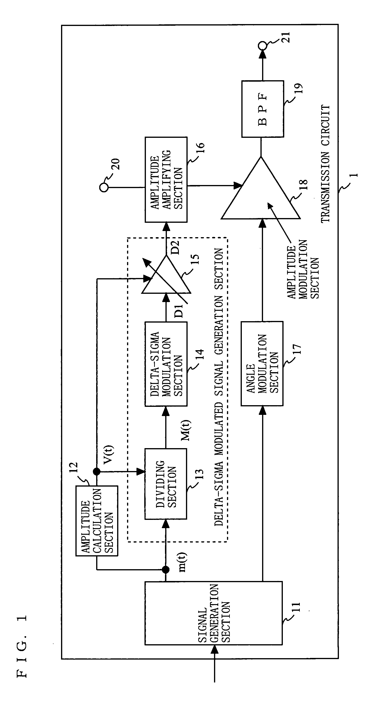
[0106]FIG. 1 is a block diagram showing an exemplary structure of a transmission circuit 1 according to a first embodiment of the present invention. As shown in FIG. 1, the transmission circuit 1 comprises a signal generation section 11, amplitude calculation section 12, dividing section 13, delta-sigma modulation section 14, variable gain amplifier section 15, amplitude amplifying section 16, angle modulation section 17, amplitude modulation section 18, band-pass filter (BPF) 19, power supply terminal 20, and an output terminal 21. The signal generation section 11 generates an amplitude signal m(t) and a phase signal respectively based on an amplitude component and phase component which are obtained by performing signal processing on input data. Here, the signal generation section 11 may be referred to as a polar coordinate signal generation section since the signal generation section 11 generates the amplitude signal m(t) and phase signal which are polar coordinate signals.

[0107]T...

second embodiment

[0138]FIG. 9 is a block diagram showing an exemplary structure of a transmission circuit 2 according to a second embodiment of the present invention. As shown in FIG. 9, the transmission circuit 2 comprises the signal generation section 11, the amplitude calculation section 12, the dividing section 13, the delta-sigma modulation section 14, the variable gain amplifier section 15, an amplitude amplifying section 26, the angle modulation section 17, the amplitude modulation section 18, the band-pass filter 19, the power supply terminal 20, and the output terminal 21. The transmission circuit 2 is different from the transmission circuit 1 of the first embodiment in that the amplitude amplifying section 26 has a different structure from that of the amplitude amplifying section 16. The amplitude amplifying section 26 includes a series regulator 26a and switching regulator 26b. Note that, components of the transmission circuit 2, which are identical to those of the transmission circuit 1,...

third embodiment

[0151]FIG. 12 is a block diagram showing an exemplary structure of a transmission circuit 3 according to a third embodiment of the present invention. As shown in FIG. 12, the transmission circuit 3 further comprises, as compared with the transmission circuit 1 according to the first embodiment, a multiplying section 27 subsequent to the signal generation section 11. FIG. 13 illustrates operations of the transmission circuit 3 according to the third embodiment of the present invention. Power information P indicating a magnitude of output power of the transmission circuit is outputted from a baseband, and then inputted to the multiplying section 27 (see FIG. 13(a)). In the case of, e.g., aW-CDMA system, the power information P is controlled by a base station, and a transmission power between the transmission circuit and the base station is controlled at each slot time. Note that, in the transmission circuit 3, the signal generation section 11 outputs the power information P based on i...


PUM


Abstract

Provided is a transmission circuit which is small in size, operates with high efficiency, and outputs a transmission signal having high linearity. A signal generation section 11 generates an amplitude signal m(t) and a phase signal. An angle modulation section 17 angle-modulates the phase signal to output an angle-modulated signal. An amplitude calculation section 12 outputs a discrete value signal V(t) having a plurality of discrete values corresponding to a magnitude of the amplitude signal m(t). A dividing section 13 divides the amplitude signal m(t) by the discrete value signal V(t) to output an amplitude signal M(t). A delta-sigma modulation section 14 delta-sigma modulates the amplitude signal M(t) to output a delta-sigma modulated signal. A variable gain amplifier section 15 amplifies the delta-sigma modulated signal by a gain corresponding to the discrete value signal V(t). An amplitude amplifying section 16 supplies, to an amplitude modulation section 18, a voltage corresponding to a magnitude of the delta-sigma modulated signal. The amplitude modulation section 18 amplitude-modulates the angle-modulated signal by the voltage supplied from the amplitude amplifying section 16, to output a modulation signal.

Description

BACKGROUND OF THE INVENTION[0001]1. Field of the Invention[0002]The present invention relates to a transmission circuit used for communication devices such as mobile phones and wireless LAN devices. The present invention particularly relates to a transmission circuit, which is small in size, operates with high efficiency and outputs a transmission signal having high linearity, and to a communication device using the transmission circuit.[0003]2. Description of the Background Art[0004]Communication devices such as mobile phones and wireless LAN devices are required to, regardless of a magnitude of output power thereof, secure precision of a transmission signal and operate with low power consumption. For such a communication device, a transmission circuit, which is small in size, operates with high efficiency and outputs a transmission signal having high linearity, is used. Hereinafter, conventional transmission circuits will be described.[0005]One of the conventional transmission cir...

Claims


Application Information

Patent Timeline
Patent Type & Authority Applications(United States)
IPC IPC(8): H03M3/00
CPCH03F2200/451H03F2200/504H03M3/51H03C5/00H03D3/007H03F2200/411H03F1/0227H03F1/32H03F3/19H03F3/245H03F2200/331H03F1/0205
Inventor MATSUURA, TORU
Owner INTERDIGITAL PATENT HLDG INC
Why Eureka
Try Eureka