Optical amplifying method, optical amplifying apparatus, and optical amplified transmission system using the apparatus

a technology of optical amplifier and amplifier, which is applied in the direction of electromagnetic transmission, optical transmission with multiple stages, and electromagnetic repeaters, etc., can solve the problems of disturbing the realization of the down sizing of the apparatus, deteriorating the transmission quality of the optical signal, etc., and achieve stable optical amplifier control and high-speed optical signal transmission

Active Publication Date: 2008-03-20
MOLEX INC
View PDF22 Cites 4 Cited by
  • Summary
  • Abstract
  • Description
  • Claims
  • Application Information

AI Technical Summary

Benefits of technology

[0009] An object of the invention is to provide an optical amplifying method, an optical amplifying apparatus and an optical amplified transmission system, in which the space occupied by the optical fiber may be reduced to realize the downsizing of the apparatus, and the control constant of the AGC circuit is adjusted to be an appropriate value even when the optical input power to the optical amplifier abruptly varies under operation, thus enabling high speed optical signal transmission and stable optical amplifier control.

Problems solved by technology

In this case, the optical output power per one wavelength channel largely varies (refer to FIG. 20C), thus deteriorating the transmission quality of the optical signal in the transitional period when the optical input power abruptly varies.
However, the above mentioned conventional optical amplifying apparatus cause a problem in which an additional space for locating an optical fiber in the delay portion is required, since the delay portion utilizes the optical fiber in order to delay optical signal on the transmission line, thus disturbing the realization of the down sizing of the apparatus.

Method used


Image

  • Optical amplifying method, optical amplifying apparatus, and optical amplified transmission system using the apparatus
  • Optical amplifying method, optical amplifying apparatus, and optical amplified transmission system using the apparatus
  • Optical amplifying method, optical amplifying apparatus, and optical amplified transmission system using the apparatus

Examples


first embodiment

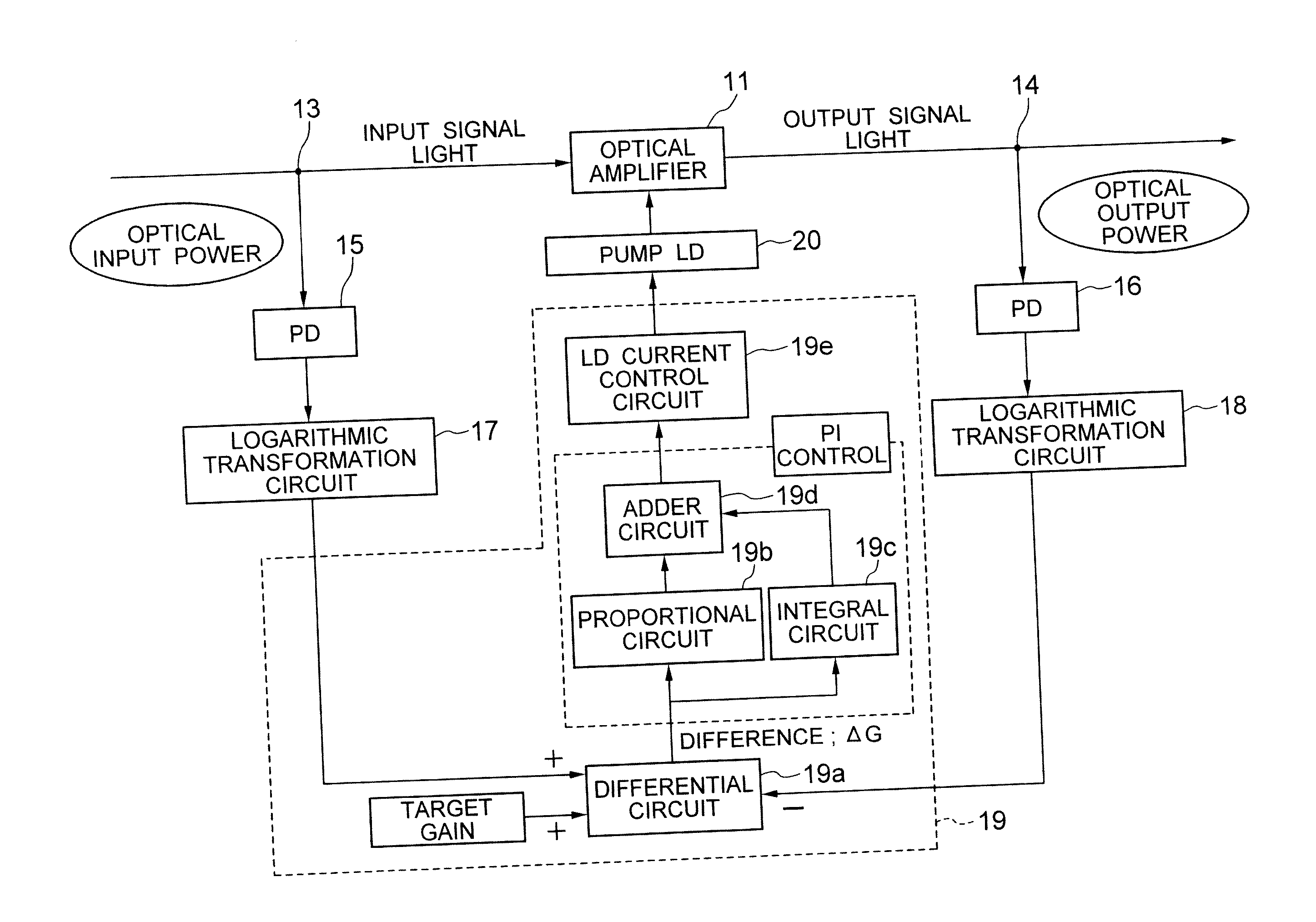
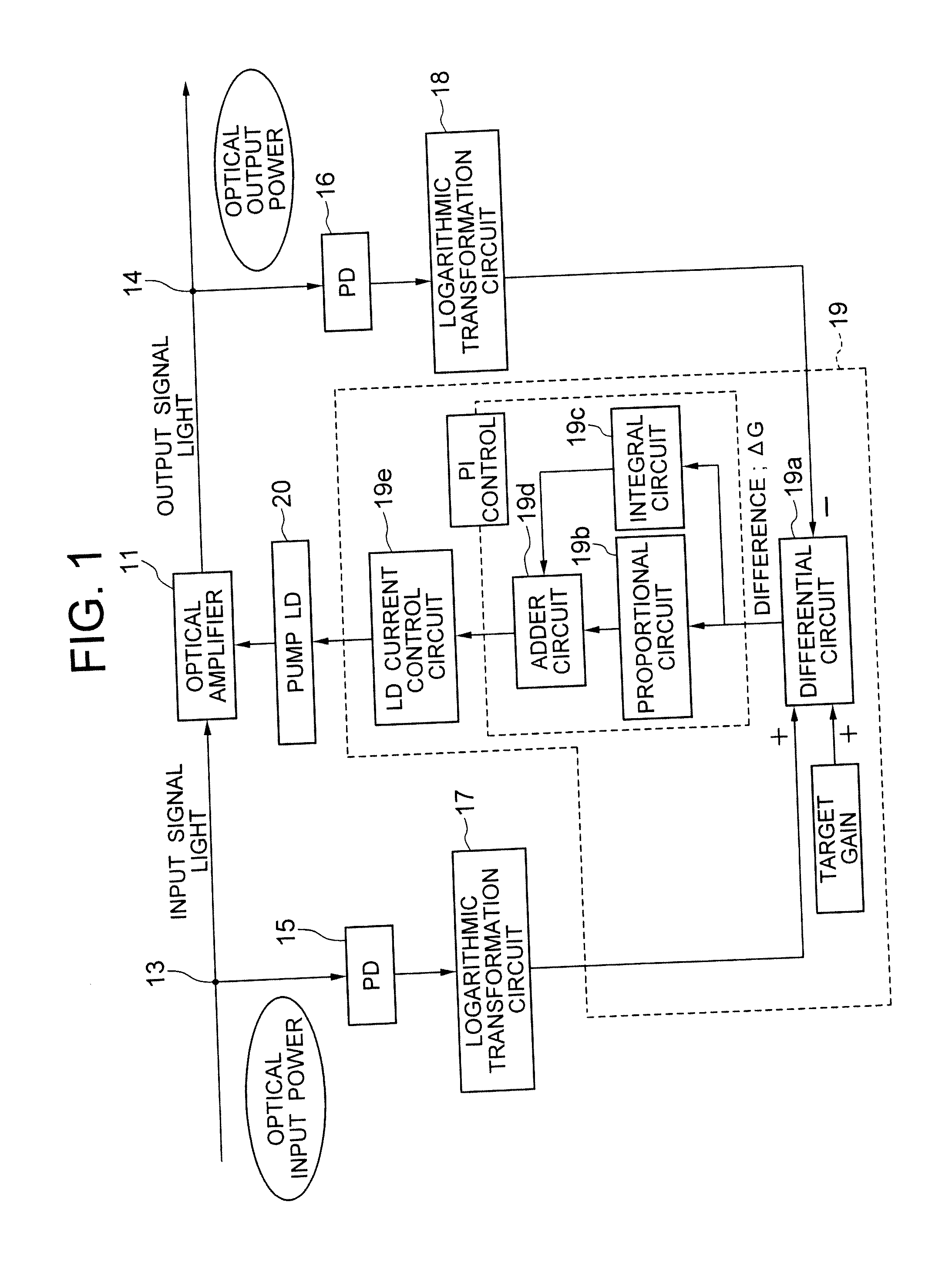
[0084]FIG. 1 is a diagram showing the first embodiment of the optical amplifying apparatus of the present invention. The automatic constant gain control (AGC) in the optical amplifying apparatus is implemented by a proportional integral control (hereinafter referred to as “PI control”), for example. A control circuit 19 implementing the AGC comprises a differential circuit 19a to which the voltages from logarithmic transformation circuits 17, 18 are inputted, a proportional circuit 19b and an integral circuit 19c to both of which a difference ΔG from the differential circuit 19a is inputted, an adder circuit 19d to which the output values from the proportional circuit 19b and the integral circuit 19c are inputted, and a laser diode current control circuit 19e to which a calculated value from the adder circuit 19d is inputted.

[0085] More specifically, the input / output power of an optical amplifier 11 is converted by a photo diode (PD) 15, 16 and a logarithmic transformation circuit ...

second embodiment

[0094] In the second embodiment of the optical amplifying apparatus of the invention, the apparatus includes a function to adjust the proportional constant of the proportional circuit in the control circuit, thus enabling to adjust the proportional constant of the proportional circuit in correspondence to the optical input power of the optical amplifier. More specifically, according to the second embodiment of the optical amplifying apparatus, the proportional constant of the proportional circuit is adjusted to be large when the optical input power is large, and the proportional constant of the proportional circuit is adjusted to be small when the optical input power is small.

[0095]FIG. 5 is a diagram describing the second embodiment of the optical amplifying apparatus of the present invention. The same numeral numbers are used in the following drawing as the elements in FIG. 1.

[0096] As shown in FIG. 5, the optical amplifying apparatus of this embodiment comprises the first stage...

third embodiment

[0112] It is proposed in the second embodiment of the apparatus that the gain is continuously adjusted by applying DCP. However, the present invention is not limited thereto, and the invention can adjust the gain of the proportional circuit by applying analog switches.

[0113]FIG. 10 is a circuit diagram showing a second example of the proportional circuit as shown in FIG. 6. As shown in FIG. 10, in the proportional circuit 19b, a plurality of resistors R21 to R2n (n is an arbitrary integer number) having different resistances in place of the DCP are connected in parallel, and each of the analog switches S1 to Sn is connected in series to the respective corresponding resistors R21 to R2n.

[0114] The gain adjusting circuit 19f controls to switch the analog switches S1 to Sn in response to the monitored optical input power so that the resistances of the resistors R21 to R2n (n is an arbitrary integer number) connected to the comparator 19b1 are changed, thus enabling to adjust the prop...


PUM


Abstract

A proportional constant adjusting circuit is arranged in the AGC circuit of the optical amplifying apparatus, and the proportional constant of the proportional circuit is continuously adjusted in correspondence to the optical input power monitored by the PD and the logarithmic transformation circuit. The AGC circuit controls the pump LD based on the monitored optical input / output power so as to control the gain of the optical amplifier to be a requested value.

Description

BACKGROUND OF THE INVENTION [0001] 1. Field of the invention [0002] The present invention relates to an optical amplifying method for adjusting control parameters in an automatic constant gain control circuit to control gain of an optical amplifier, an optical amplifying apparatus and an optical amplified transmission system using the apparatus. [0003] 2. Related Art [0004] A conventional optical amplifying apparatus 110, for example as shown in FIG. 19, includes an optical amplifier 111 connected to an optical transmission line 101. An optical signal inputted into the optical amplifier 111 and an optical signal outputted from the optical amplifier 111 and passed through an erbium-doped fiber (EDF) 112 are divided by optical couplers 113, 114 respectively, and then optical input power and optical output power thereof are detected by photo diodes (PD) respectively in the optical amplifying apparatus 110. The optical input power and the optical output power are converted to voltages c...

Claims


Application Information

Patent Timeline
Patent Type & Authority Applications(United States)
IPC IPC(8): H01S3/094H01S3/10H04B10/12H01S3/00H01S3/06H01S3/067H01S3/0941H01S3/131H04B10/07H04B10/29H04B10/293H04B10/296H04B10/564H04B10/572
CPCH01S3/094003H01S3/1312H04B2210/003H04B10/296H01S2301/04
Inventor KAWAHARA, RYOFUKUSHIMA, MASARUKAGI, NOBUYUKISEKIYA, KENSAKU
Owner MOLEX INC
Why Eureka
Try Eureka