Ultrasonic transducer driving circuit and ultrasonic diagnostic apparatus

a technology of ultrasonic transducer and driving circuit, which is applied in the direction of pulse technique, instruments, applications, etc., can solve the problems of large circuit size, short circuit time, and the output voltage does not quickly return from the positive or negative voltage to the ground voltage, so as to improve the performance of ultrasonic diagnostic apparatus, reduce the size of the ultrasonic transducer driving circuit, and reduce the size of the circuit

Inactive Publication Date: 2008-03-20
GE MEDICAL SYST GLOBAL TECH CO LLC
View PDF6 Cites 36 Cited by
  • Summary
  • Abstract
  • Description
  • Claims
  • Application Information

AI Technical Summary

Benefits of technology

[0022]In the ultrasonic diagnostic apparatus according to the above eighth aspect, the size of the ultrasonic transducer driving circuit can be reduced.
[0023]According to the ultrasonic transducer driving circuit and the ultrasonic diagnostic apparatus of the present invention, the voltage on the output line can quickly be returned from the positive voltage or negative voltage to the ground voltage. Besides, the circuit size can be reduced.
[0024]The ultrasonic transducer driving circuit and the ultrasonic diagnostic apparatus of the present invention can be utilized to improve the performance of ultrasonic diagnostic apparatus and reduce the size thereof.

Problems solved by technology

The above ultrasonic diagnostic apparatus of prior art has a problem in which, when a pulse of a positive voltage or negative voltage is applied to the output line, the voltage on the output line does not quickly return from the positive voltage or negative voltage to the ground voltage because of capacitance of the output line.
However, a FET with a capacity of 1 A or more is needed in the active ground clamp circuit and this poses a problem that the circuit size becomes larger.

Method used


Image

  • Ultrasonic transducer driving circuit and ultrasonic diagnostic apparatus
  • Ultrasonic transducer driving circuit and ultrasonic diagnostic apparatus
  • Ultrasonic transducer driving circuit and ultrasonic diagnostic apparatus

Examples


embodiment 1

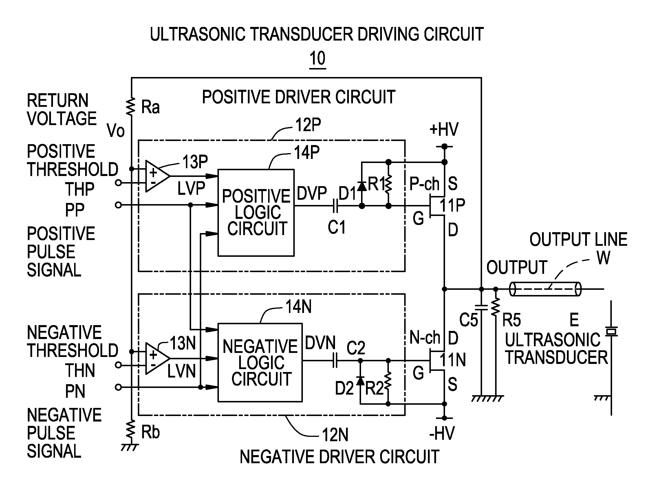
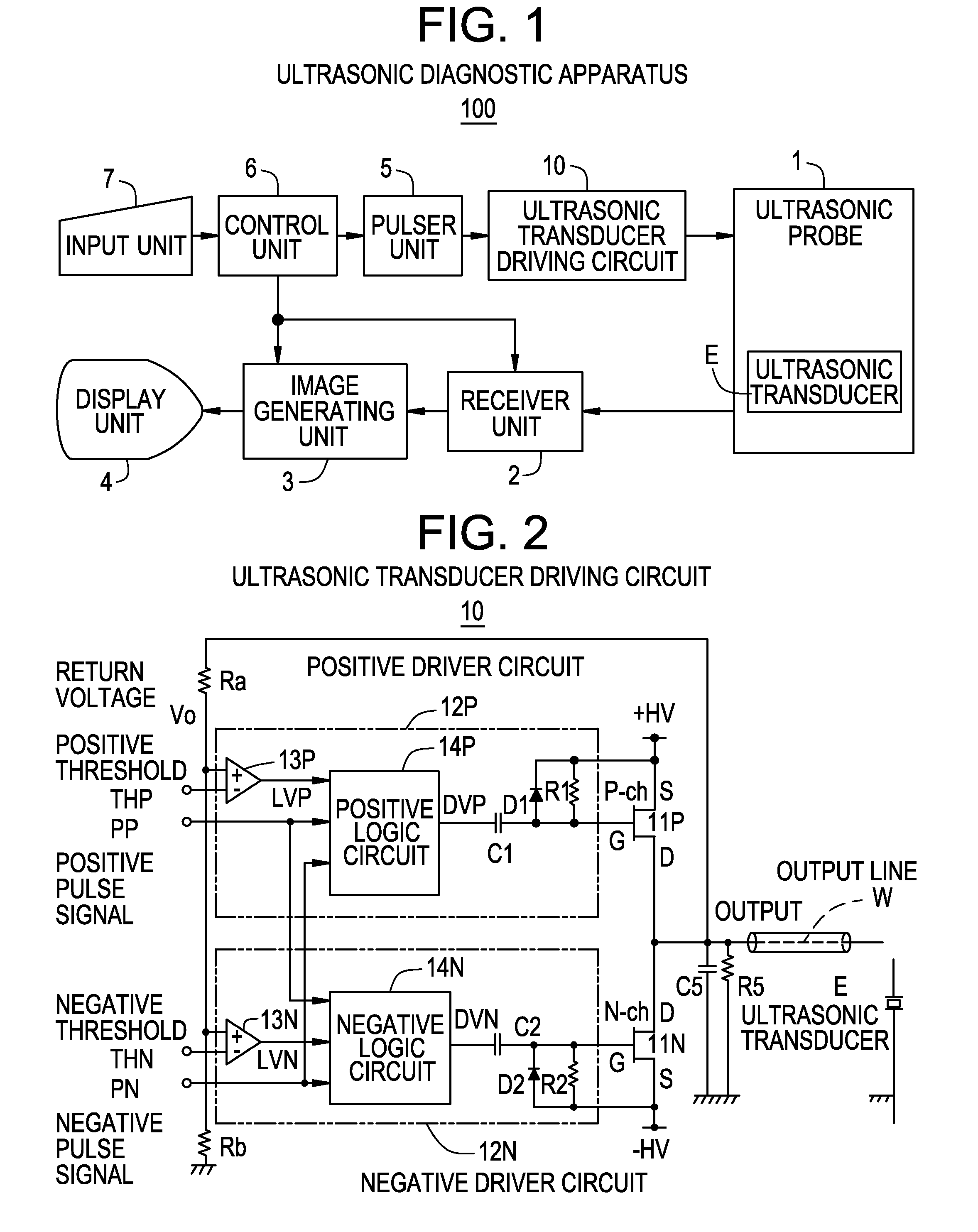
[0034]FIG. 1 is a structural diagram showing an ultrasonic diagnostic apparatus 100 relevant to Embodiment 1.

[0035]This ultrasonic diagnostic apparatus 100 comprises an ultrasonic probe 1 within which multiple ultrasonic transducers E are installed to transmit ultrasonic pulses from the transducer into a specimen body and receives ultrasonic echoes from within the specimen body, a receiver unit 2 which generates and outputs an acoustic beam signal from the ultrasonic echoes, an image generating unit 3 which generates an ultrasonic image based on the acoustic beam signal, a display unit which displays the ultrasonic image, an ultrasonic transducer driving circuit 10 which drives the ultrasonic transducer E for transmitting the ultrasonic pulses, a pulser unit 5 which inputs a signal for transmission to the ultrasonic transducer driving circuit 10, a control unit which takes overall control of the apparatus, and an input unit 7 which is used for an operator to operate the apparatus.

[0...

embodiment 2

[0052]The present invention can be applied in the same manner as for Embodiment 1, when the negative voltage −HV is applied to the ultrasonic transducer E, followed by a return to the ground voltage and application of the positive voltage +HV, and even when the negative voltage −HV is applied to the ultrasonic transducer E, followed by application of the positive voltage +HV.


PUM


Abstract

With the aim of quickly returning the voltage of an output line to an ultrasonic transducer from a positive voltage or a negative voltage to the ground voltage and reducing the circuit size, immediately after turning on and turning off of a positive FET in accordance with a positive pulse signal, a negative FET goes on for only a pull-back period allowing for the output line to return to the ground voltage. Also, immediately after turning on and turning off of the negative FET in accordance with a negative pulse signal, the positive FET goes on for only a pull-back period allowing for the output line to return to the ground voltage.

Description

BACKGROUND OF THE INVENTION[0001]The present invention relates to an ultrasonic transducer driving circuit and an ultrasonic diagnostic apparatus and, more particularly, relates to an ultrasonic transducer driving circuit and an ultrasonic diagnostic apparatus that make it possible to quickly return, from a positive voltage or negative voltage to a ground voltage, the voltage of an output line which outputs the positive voltage or the negative voltage or the ground voltage to an ultrasonic transducer, and that allow for a reduction in circuit size.[0002]Heretofore, there is known an ultrasonic diagnostic apparatus including a positive FET (Field Effect Transistor) which outputs a positive voltage onto an output line to an ultrasonic transducer at on state, a negative FET which outputs a negative voltage onto the output line to the ultrasonic transducer at on state, and a driver circuit which turns the positive FET and the negative FET on / off (e.g., see Patent Document 1 and Patent D...

Claims


Application Information

Patent Timeline
Patent Type & Authority Applications(United States)
IPC IPC(8): A61B8/00H01L41/09
CPCG01S7/52023H03K17/6874H03K17/04206G01S15/8909G01N29/24A61B8/00
Inventor AMEMIYA, SHINICHI
Owner GE MEDICAL SYST GLOBAL TECH CO LLC
Why Eureka
Try Eureka