Reusable Inversion Sleeve Assembly for Inversion of Cured in Place Liners

a sleeve assembly and sleeve assembly technology, which is applied in the direction of auxillary shaping apparatus, pipe elements, butter manufacture, etc., can solve the problems of near the pipe joint, and the deterioration of the pipe itsel

Active Publication Date: 2008-03-27
INA ACQUISITION
View PDF5 Cites 5 Cited by
  • Summary
  • Abstract
  • Description
  • Claims
  • Application Information

AI Technical Summary

Benefits of technology

[0023] Generally speaking, in accordance with the invention, an inversion sleeve assembly for installation of a cured in place liner with a rigid gland apparatus is provided. The inversion sleeve assembly includes a tubular flexible sleeve and a cylindrical banding boot having an inlet port for introducing inversion and / or curing fluid at the distal end of the sleeve. The sleeve and the inversion boot are of the same dimension as the cured in place pipe liner to be inverted. The assembly is used with an installation apparatus having a frame with at least one selectively operable rigid gland upstream of the banding boot. The sleeve passes between a rigid gland used to form a fluid seal. The flexible inversion sleeve may have an installed curing fluid inlet for use with an apparatus having two rigid glands. In this case, the inlet on the sleeve is located between the two glands with the banding boot downstream of the lower gland. In a preferred embodiment the flexible sleeve is a length of dry cured in place liners of the same dimension as the liner being installed. The sleeve has at least one layer of impregnated material and an outer impermeable layer. The impregnable material holds lubricant to aid in the installation and the sleeve assembly is reusable.

Problems solved by technology

It is generally well known that conduits or pipelines, particularly underground pipes, such as sanitary sewer pipes, storm sewer pipes, water lines and gas lines that are employed for conducting fluids frequently require repair due to fluid leakage or deterioration.
The leakage may be due to improper installation of the original pipe, or deterioration of the pipe itself due to normal aging or to the effects of conveying corrosive or abrasive material.
Cracks at or near pipe joints may be due to environmental conditions such as earthquakes or the movement of large vehicles on the overhead surface or similar natural or man made vibrations, or other such causes.
Regardless of the cause, such leakage is undesirable and may result in waste of the fluid being conveyed within the pipeline, or result in damage to the surrounding environment and possible creation of a dangerous public health hazard.
If the leakage continues it can lead to structural failure of the existing conduit due to loss of soil and side support of the conduit.
Because of ever increasing labor, energy and machinery costs, it is increasingly more difficult and less economical to repair underground pipes or portions that may be leaking by digging up and replacing the pipes.
The eversion tower, which was time consuming to construct, caused workers to be 30 feet above the ground often near trees and electrical wires.
The major disadvantage to the use of these apparatuses with water is the quantity and availability of the inverting water.
There is limit on how much pressure can be used to invert a liner without adversely affecting the quality of the installed CIPP liner and / or damaging to the existing conduit.
This in turn causes an increase on the friction between the inverting CIPP liner and gland.
However, the process described does not provide for use of a lay flat hose for introduction of steam.
Moreover, use of a puncturing canister disclosed in these patents is not suitable for medium and large diameter liners.

Method used


Image

  • Reusable Inversion Sleeve Assembly for Inversion of Cured in Place Liners
  • Reusable Inversion Sleeve Assembly for Inversion of Cured in Place Liners
  • Reusable Inversion Sleeve Assembly for Inversion of Cured in Place Liners

Examples


Embodiment Construction

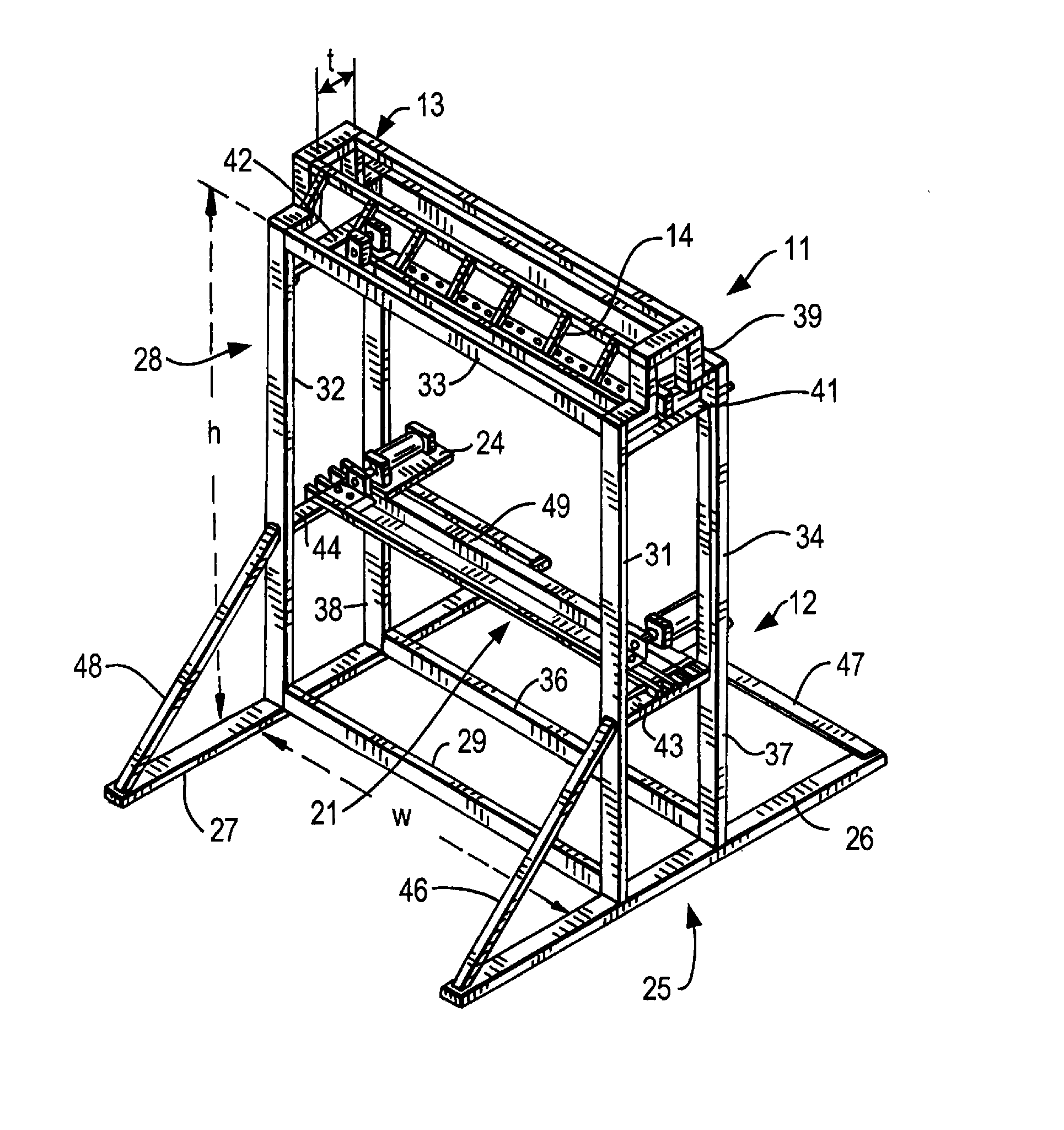
[0041] An improved method and apparatus for air inverting and steam curing a CIPP liner in compliance with ASTM F1216 Standard Practice for Rehabilitation of Existing Pipelines and Conduits by the Inversion and Curing of a Resin-Impregnated Tube is described. The method and apparatus described herein are well suited for the installation of medium diameter CIPP liners working from the surface through structures, such as manholes to rehabilitate existing buried pipelines and conduits.

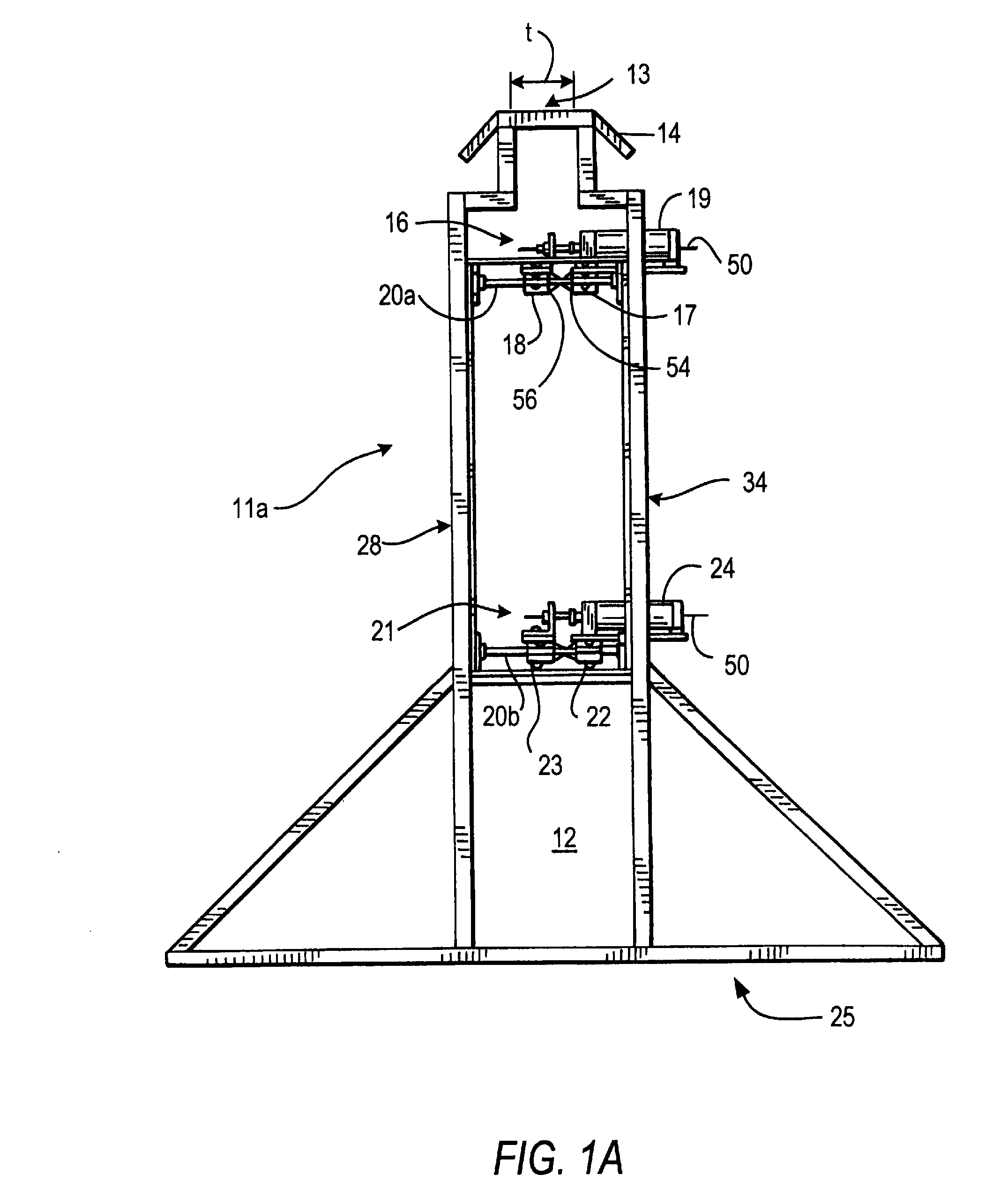
[0042] An inverting apparatus 11 having a single rigid lower gland 21 constructed and arranged in accordance with the invention is shown in FIG. 1. In FIG. 1A, a similar apparatus 11a having an upper gland 16 and lowe gland 21 is shown. In view of the similarity of elements, the same reference numeral are used in FIGS. 1 and 1A to describe identical elements.

[0043] Apparatuses 11 and 11a are rigid frames dimensioned to be positioned over the inverting access to the conduit to be lined. Apparatuses 11 an...


PUM

PropertyMeasurementUnit
diameteraaaaaaaaaa
diameteraaaaaaaaaa
diameteraaaaaaaaaa

Abstract

Installation of a flexible cured in place liner by inverting the liner utilizing an inversion sleeve assembly with an installation apparatus having at least one selectively operable rigid gland. The sleeve assembly includes a sleeve portion of an absorbable material secured in an apparatus with an inversion boot fitted at the distal end with an inlet port for inversion and/or curing fluid. The sleeve assembly and apparatus are particularly well suited for inverting with air and curing the liner with steam introduced through a perforated lay flat hose using an apparatus with two glands. The installation sleeve is the same dimension as the liner to be installed and is reusable thereby substantially reducing the set up time to install using the dual gland apparatus. Preferably, the flexible sleeve is a length of dry cured in place liner inverted on to itself to expose two impregnable surfaces. The sleeve may have a built in fluid inlet port for use with a dual gland apparatus.

Description

CROSS REFERENCE TO RELATED APPLICATION [0001] This application is based on and claims the benefit of co-pending provisional application Ser. No. 60 / 840,818, filed Aug. 29, 2006, the contents of which is incorporated herein by reference in its entirety.BACKGROUND OF THE INVENTION [0002] This invention relates to a reusable inversion sleeve assembly for installing a cured in place liner with an apparatus having at least one rigid gland. The methods and apparatus reduce the time needed to set up a wet out cured in place liner for installations using air for inversion and steam for curing and use of a dual gland apparatus allowing use of a hold back strap and a lay flat hose for introduction of steam. [0003] It is generally well known that conduits or pipelines, particularly underground pipes, such as sanitary sewer pipes, storm sewer pipes, water lines and gas lines that are employed for conducting fluids frequently require repair due to fluid leakage or deterioration. The leakage may ...

Claims


Application Information

Patent Timeline
Patent Type & Authority Applications(United States)
IPC IPC(8): F16L55/18F16L55/163
CPCB29C63/36F16L55/1654F16L55/1651F16L55/162F16L55/163F16L55/18
Inventor DRIVER, FRANKLIN THOMASBIRCHLER, NEIL T.COSTA, KYLE M.POLIVKA, RICHARD C.WANG, WEIPING
Owner INA ACQUISITION
Why Eureka
Try Eureka